


16
• The set screws in the table supports have
been loosened and readjusted (see page 9).
• The sander has been leveled (page 11).
• Moving parts of the height adjustment
mechanism are well lubricated, including
miter gears, columns, and threaded
adjusting screws.
If the table height mechanism still does not
operate smoothly, try the following:
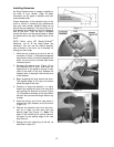
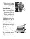
1. Further loosen the set screws on the front of
the table supports (see Figure 5).
2. Lubricate thoroughly by applying penetrating
lubricant to the table supports where they
contact the columns, and to all contact
points of adjusting screws and transfer rod
(see Figure 1). Also apply grease to the
miter gears.
3. If the height adjustment still feels stiff, check
for misalignment of adjusting screw
supports and table supports which could
cause binding on the adjusting screws. The
adjusting screw supports can be adjusted by
loosening the set screws which secure them
to the columns, and rotating the supports to
proper position.
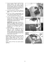
4. Check the miter gear alignment. The miter
gears can be adjusted on their shafts by
prying off their protective caps with a flat
blade screwdriver, and loosening the set
screws on the gears. Check that the gear
mesh is not too tight or too loose, and that
the gear teeth align with the opposing gear.
Note that the collars located on the transfer
rod (see Figure 1, page 7) should be
positioned to control the lateral movement of
the transfer rod to maintain accurate miter
gear alignment and mesh.
The mesh of the miter gears should be
smooth and even. If it is not, adjust the
gears for good mesh. Test for smooth
operation.
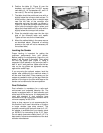
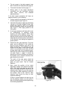
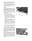
5. Next, check the position of the height
adjustment screws: First raise the conveyor
table. Then check the retaining ring at the
top of the height adjustment screw on the
outboard side (Figure 24), and the retaining
ring under the height adjustment handle on
the inboard side of the machine. Both
retaining rings should be snug on their
respective bearings.
If there is a space between the retaining ring
and the bearing, tighten one set screw in
each of the table supports before performing
the following adjustment:
Figure 24