


21
Step 2: Now repeat Step 1 on the right (inboard)
side of conveyor. Compare the measurements
from side to side. If they are not equal, loosen
one of the brackets that hold the roller in place.
Tip this bracket until the distance between the
roller and the straight-edge are equal from side
to side, then tighten the bracket.
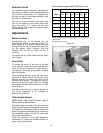
Tension Roller Adjustment
Snipe marks result from too much tension roller
pressure and are identified as a visible line
running across the width of the board
approximately 2-1/4” from the end of the board.
If a snipe mark occurs on the leading edge of
the board, adjust the outfeed tension roller. If a
snipe mark occurs on the trailing end of the
board, adjust the infeed tension roller.
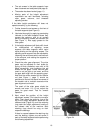
Tension roller pressure can be decreased in one
of two ways:
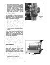
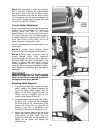
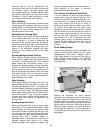
Method 1: Loosen spring retaining screws
(Figure 34). Do not disengage screws entirely.
Method 2: Raise height of tension rollers as
follows. Repeat “Initial Drum Alignment”
procedure (page 18), using the drum alignment
templates under the drum, except place a few
sheets of paper under the tension roller(s)
needing adjustment. Do NOT place the paper
under the drum or alignment templates. Tighten
bolts. Repeat this procedure until the snipe is
eliminated.
Improperly adjusted tension
rollers (i.e. those set too high, rendering
them non-functional) could allow kickback or
slippage of pieces being sanded.
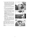
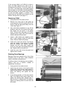
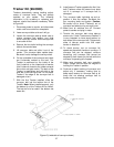
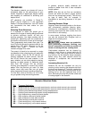
Adjusting Table Supports
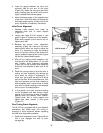
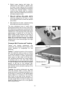
1. If the conveyor table does not rise and lower
easily, measure the distance between the
top of the base column support and the
bottom of the table support on both the
inboard and the outboard side of the
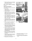
machine. See Figures 35 and 36.
2. Compare these measurements; they should
be within 1/16”. If they are not, disengage
the miter gear on the inboard side of the
transfer rod (Figure 35) by prying off the
protective cap with a screwdriver and
loosening the set screw in the gear’s collar.
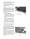
3. Adjust the conveyor table height using the
height adjustment handle to get the same
measurement on both sides. Then re-
engage the miter gear on the transfer rod,
tighten the set screw, and replace the
protective cap.
Figure 34
Figure 35
Figure 36