


18
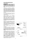
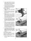
3. Insert the gauge between the drum and
conveyor bed at one end of the drum
(Figure 26). Raise the conveyor bed while
slowly rotating drum by hand until the drum
lightly contacts the thickness gauge.
4. Move thickness gauge to the opposite end
of the drum. If the drum does not contact the
thickness gauge equally at both ends of the
drum, alignment is necessary. See below.
Initial Drum Alignment
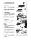
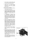
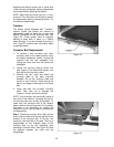
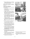
1. Release v-belt tension from motor by
loosening pinch bolt of motor support
(Figure 27).
2. Loosen two lower #10-32 screws in belt
guard (Figure 27 shows one of the screws).
Slide motor support up the column and re-
tighten pinch bolt.
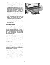
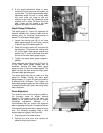
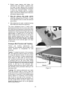
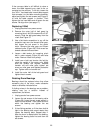
3. Because the tension roller suspension
assembly (Figure 28) mounts to the drum
bearing bolts which are used to adjust the
drum, it is necessary to align the sanding
drum and tension rollers at the same time.
Loosen outboard bearing bolt knobs (Figure
28) and the inboard bearing bolts.
4. With all four bearing bolts loosened, note
that the drum will adjust about 1/2” on each
end. Position drum alignment templates
(Figure 28) on the conveyor and below the
drum with one template at each end of the
drum.
5. Raise the conveyor bed so that the drum is
resting on both templates but leaving the
drum within its range of adjustment. To
check this, you should be able to lift either
end of the drum off the templates and, with
light hand pressure on the drum, attempt to
slide templates with a screw driver to make
sure drum is actually resting on the template
and not just in its lowest position.
6. In this position, the drum should be resting
on the templates and both tension rollers
resting on the conveyor surface. Re-tighten
bearing bolts and restore v-belt tension.
Tighten pinch bolt in motor support and
tighten two lower screws in belt guard
(Figure 27).
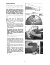
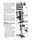
Fine-Tuning Drum Alignment
The 22-44 Pro is equipped with a drum adjuster
mechanism that allows easy fine tuning or
changing of drum alignment without repeating
the intial drum alignment procedure.
1. Raise drum adjustment lever (Figure 29) so
that it just engages the side of drum
carriage leg.
Figure 27
Figure 28
Figure 29