


A-3
INSTALLATION
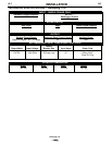
SELECT SUITABLE LOCATION
Locate the welder in a dry location where there is free
circulation of clean air into the louvers in the back and
out the front of the unit. A location that minimizes the
amount of smoke and dirt drawn into the rear louvers
reduces the chance of dirt accumulation that can block
air passages and cause overheating.
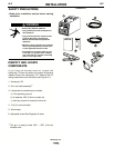
STACKING
Handymig 170i’s cannot be stacked.
TILTING
Each machine must be placed on a secure, level sur-
face, either directly or on the recommended cart. The
machine may topple over if this procedure is not fol-
lowed.
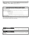
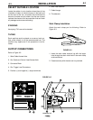
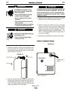
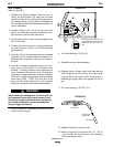
OUTPUT CONNECTIONS
Refer to Figure A.2.
1. Work Cable Access Hole.
2. Gun Cable and Control Lead Access Hole.
3. Connector Block.
4. Gun Trigger Lead Connectors.
5. Positive (+) and negative (–) output terminals.
6. Wire Feed Gearbox.
7. Cable Hanger.
8. Thumbscrew.
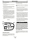
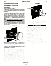
Work Clamp Installation
Attach the work clamp per the following: Refer to
Figure A-3.
Handymig 170i
1
2
E
WELDING AMP RANGE
30-70
4
5
8
3
6
7
+
-
9
10
FIGURE A.3
1. Insert the work cable terminal lug with the larger
hole through the strain relief hole in the work clamp
as shown above.
2. Fasten securely with the bolt and nut provided.
FIGURE A.2
A-3
Handymig 170i