


A-5
INSTALLATION
BE SURE TO KEEP YOUR FACE AWAY FROM THE
VALVE OUTLET WHEN “CRACKING” THE VALVE.
Never stand directly in front of or behind the flow
regulator when opening the cylinder valve. Always
stand to one side.
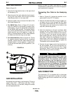
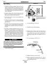
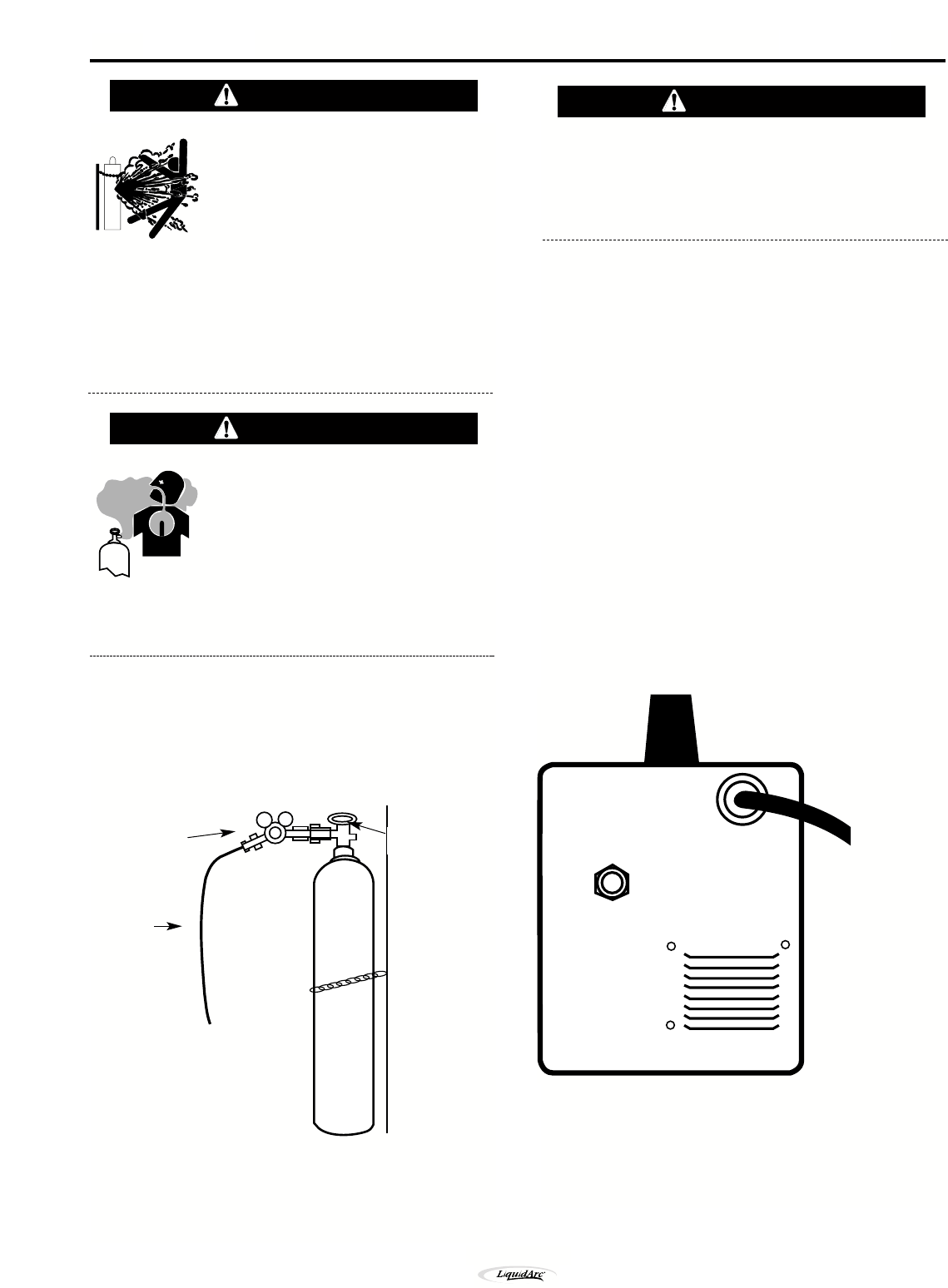
3. Attach the flow regulator to the cylinder valve and
tighten the union nut securely with a wrench..
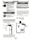
4. Refer to Figure A.6. Attach one end of inlet gas
hose to the outlet fitting of the flow regulator and
tighten the union nut securely with a wrench.
Connect the other end to the Handymig 170i Gas
Solenoid Inlet Fitting (5/8-18 female threads — for
CGA — 032 fitting). Make certain the gas hose is
not kinked or twisted.
5. Reinstall case side before connecting input power.
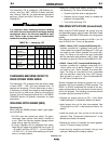
INPUT CONNECTIONS
FIGURE A.6
Refer to Figure A.6.
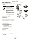
CYLINDER may explode if dam-
aged. Keep cylinder upright and
chained to support
• Keep cylinder away from areas
where it may be damaged.
• Never lift welder with cylinder
attached.
• Never allow welding electrode to
touch cylinder.
• Keep cylinder away from welding
or other live electrical circuits.
BUILDUP OF SHIELDING GAS may
harm health or kill.
• Shut off shielding gas supply
when not in use.
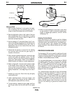
1. Chain the cylinder to a wall or other stationary sup-
port to prevent the cylinder from falling over.
Insulate the cylinder from the work circuit and earth
ground. Refer to Figure A.5.
FIGURE A.5
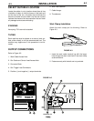
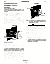
2. With the cylinder securely installed, remove the
cylinder cap. Stand to one side away from the out-
let and open the cylinder valve very slightly for an
instant. This blows away any dust or dirt which may
have accumulated in the valve outlet.
WARNING
Cylinder Valve
Gas Hose
Flow Regulator
WARNING
WARNING
POWER INPUT
CABLE
GAS SOLENOID
INLET FITTING
A-5
Handymig 170i