


A-4
A-4
INSTALLATION
Work Cable Installation
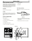
Refer to Figure A.2.
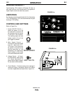
1. Open the wire feed section door on the right side of
the Handymig 170i.
2. Pass the end of the work cable that has the termi-
nal lug with the smaller hole through the Work
Cable Access Hole (1) in the case front.
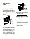
3. Route the cable under and around the back of the
Wire Feed Gearbox (6).
4. For GMAW Only: Refer to Figure A.2. As deliv-
ered, the machine is connected for positive elec-
trode polarity. This is the appropriate configuration
for the GMAW (MIG) process. To complete installa-
tion, use the provided wing nut to connect the work
cable’s terminal lug to the negative (–) output ter-
minal (5) located above the Wire Feed Gearbox
(6). Make sure that both wing nuts are tight.
5.
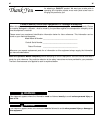
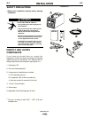
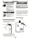
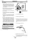
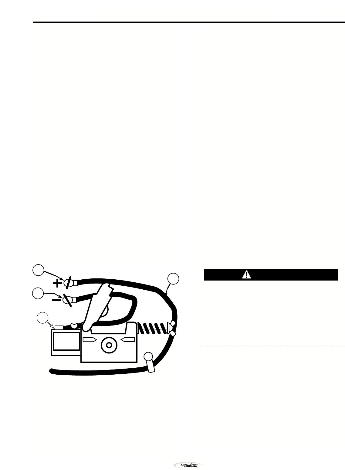
For Innershield Only: Refer to Figure A.4. To wire
for negative polarity (required for the Innershield
process), connect the short cable attached to the
connector block (1) to the negative (–) output termi-
nal (2) and the work cable (3) to the positive (+) ter-
minal (4).
FIGURE A.4
NOTE: If .035" or .045" (0.9 mm or 1.2 mm)
Innershield flux-cored wire is to be used, the appropri-
ate Innershield kit is required.
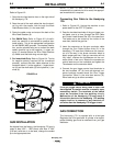
Connecting Gun Cable to the Handymig
170i.
1. Refer to Figure A.2. Unplug the machine or turn
power switch to the OFF “O” position.
2. Pass the insulated terminals of the gun trigger con-
trol leads, one at a time, through the Gun Cable
and Control Lead Access Slot (2) in the case front.
The leads are to be routed up the inside of the
case front, behind the gas line.
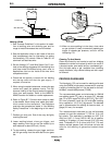
3. Insert the connector on the gun conductor cable
through the Gun Cable Access Hole (2) in the
Handymig 170i case front. Make sure the connec-
tor is all the way in the brass connector block to
obtain proper gas flow. If the gun connector will not
fully insert, unscrew the thumbscrew on the con-
nector block a few turns. Rotate the connector so
control leads are on the underside and tighten the
Thumbscrew on the connector block.
4. Connect the gun trigger control lead terminals to
the two insulated 1/4" (6,4 mm) tab terminal con-
nector bushings located above the “Gun Trigger
Connection” decal in the wire feed section (4).
Either lead can go to either connector.
If the gun trigger switch being used is other than
that supplied, the switch must be a normally open,
momentary switch. The terminals of the switch
must be insulated from the welding circuit.
Malfunction of the Handymig 170i may result if
this switch shorts to the Handymig 170i welding
output circuit or is common to any electrical cir-
cuit other than the Handymig 170i trigger circuit.
GAS CONNECTION
The Handymig 170i is supplied with a mixed gas
Regulator and a 3m gas hose. A cylinder of an appro-
priate shielding gas must be obtained from your gas
distributor.
CAUTION
GUN INSTALLATION
As shipped from the factory, the Handymig 170i gun is
ready to feed .023" – .025"(.6mm) solid wire. If .030"
(0.8 mm) solid wire is to be used, change the contact
tip to the appropriate size.
2
4
3
1
Handymig 170i