


B-3
OPERATION
WELDING OPERATIONS
SEQUENCE OF OPERATION
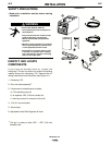
Wire Loading
Refer to Figure B.2 and B.3.
The machine power switch should be turned to the
OFF (“O”) position before working inside the wire feed
enclosure.
The machine is shipped from the factory ready to feed
8” (200 mm) diameter spools [2.2” (56 mm) max.
width]. These spools fit on a 2” (50 mm) diameter
spindle that has a built-in adjustable friction brake to
prevent overrun of the spool and excess slack in the
wire.
Note:When loading and removing the 8” Spools
make
sure that the wing nut (inside the wire spool spindle
hub) is turned 90° from the wire spool spindle locking
tab. If the wing nut is positioned in line with the locking
tab, the tab cannot be depressed to load or unload
the wire spool.
Load an 8” (200 mm) diameter spool on the wire spool
spindle shown in Figure B.2.
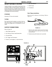
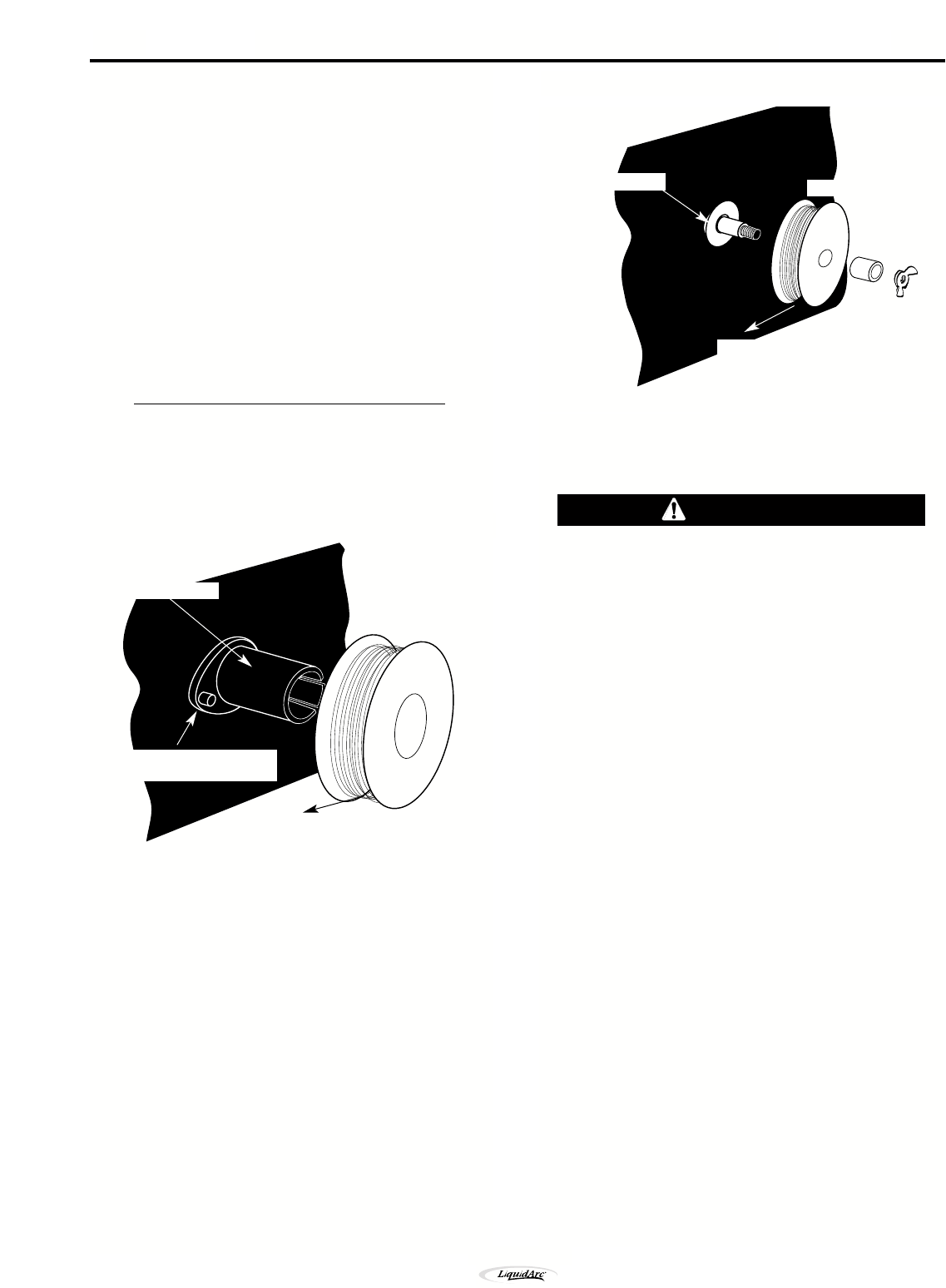
To use 4” (100 mm) diameter spools, the 2” (50 mm)
diameter spindle must be removed (See Figure B.3).
Remove the wing nut and spacer at the end of the
shaft and remove the outside plastic wire spool spin-
dle. The spindle can be stored in the wire feed com-
partment. A 4” (100 mm) diameter spool is mounted
directly on the 5/8” (16 mm) diameter shaft and held in
place with the previously removed hardware. Also
make certain the start end of the wire, which may pro-
trude through the side of the spool does not contact
any metallic case parts.
Note: The brake should be adjusted with a spool of
wire installed. When properly adjusted it should
move freely but not coast.
Some spools can have the start wire protruding
from the side of the spool. This must be insulated
from internal metal components otherwise electri-
cal grounding faults will result and the machine
will be seriously damaged.
Friction Brake Adjustments
1. With wire spool installed, check free movement
and coast of the spool.
2. To tighten the brake turn the wing nut clockwise in
1/4 turn increments until coasting stops.
3. To loosen the brake turn the wing nut counter-
clockwise in 1/4 turn increments until the wire spool
moves freely without coasting.
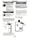
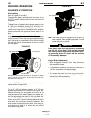
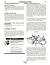
FIGURE B.2
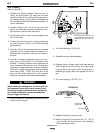
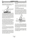
FIGURE B.3
Wire Spool must be pushed all the way on the spindle so that the
spindle’s tab will hold it in place. The Wire Spool will rotate clock-
wise when wire is dereeled.
8” Wire Spool
To Wire Drive
Wire Spool Spindle
Be sure that this stud engages
the hole in the wire spool.
Wire Spindle Shaft
4" Wire Spool
Wing Nut
and Spacer
To wire drive
CAUTION
B-3
Handymig 170i