


D-4D-4
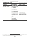
GROUND TEST PROCEDURE
WARNING ELECTRIC SHOCK can kill
WARNING: This procedure is only suitable for applica-
tions using DC mega testers up to 500V.
Note: This procedure is for ‘machines as built’ many
modifications could have taken place over the life of a
particular machine, so details of this procedure may
need to be ‘adjusted’ to suit these modifications.
For prompt service contact your local authorised Liquid
Arc Field Service shop.
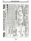
The insulation resistance values listed below are from
Australian Standard AS1966.1.
• Disconnect input power by removing plug from mains
supply.
• Remove welding leads (gun and work lead) from the
machine before any tests are carried out.
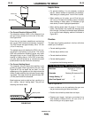
• Remove plug from PCB, install a shorting socket into
the harness plug. (The shorting socket is to have pins
4 & 5 jumpered together and all other pins jumpered
together separately and insulated.)
• Connect a shorting jumper across the connections to
the capacitor and from the capacitor to each rectifier
heat sink plate.
• Set power switch to ‘on’ position.
• Input circuit test: Connect one lead of the mega tester
to the frame of the machine and the other lead to
both the ‘active’ & ‘neutral’ terminals of the 240V
input plug. Apply the test. (Minimum resistance 1M•)
• Welding circuit test: Connect one lead of the mega
tester to the frame of the machine and the other lead
to the positive output stud. Apply the test. (Minimum
resistance 1M•)
• Auxiliary circuit test: Connect one lead of the mega
tester to the frame of the machine and the other lead
to jumper on pins 4 & 5 in the shorting socket. Apply
the test. (Minimum resistance 1M•)
• Input circuit to welding circuit test: Connect one lead-
of the mega tester to both the ‘active’ & ‘neutral’ ter-
minals of the 240V input plug and the other to the
positive output stud. Apply the test(s). (Minimum
resistance 10M•)
• Input circuit to auxiliary circuit test: Connect one lead-
of the mega tester to both the ‘active’ & ‘neutral’ ter-
minals of the 240V input plug and the other to the
jumper on pins 4 & 5 in the shorting socket. Apply the
test. (Minimum resistance 1M•)
• Welding circuit to auxiliary circuit test: Connect one-
lead of the mega tester to the positive output stud
and the other to the jumper on pins 4 & 5 in the
shorting socket. Apply the test. (Minimum resistance
1M•)
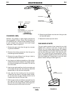
• Wire drive test: Connect one lead of the mega tester-
to the positive output stud and the other to the drive
roll shaft. Apply the test. (Minimum resistance 1M•)
• Remove all harness shorting plugs and connect all
plug and leads to PCB. Remove all shorting jumpers.
If any problems are encountered, refer to your near-
est authorised Liquid Arc Field Service Shop.
WARNING
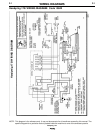
Handymig 170i