


D-2D-2
MAINTENANCE
COMPONENT
REPLACEMENT
PROCEDURES
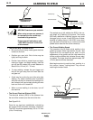
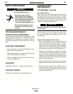
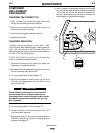
CHANGING THE CONTACT TIP
1. Refer to Figure D.2. Remove the gas nozzle from
the gun by unscrewing counter-clockwise.
2. Remove the existing contact tip from the gun by
unscrewing counter-clockwise.
3. Insert and hand tighten desired contact tip.
4. Replace gas nozzle.
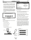
CHANGING DRIVE ROLL
The drive roll has two grooves; one for .023" – .025"
(0.6 mm) solid steel electrode and a larger groove for
.030" (0.8 mm) solid and .035" (0.9 mm) flux-cored
steel electrode. As shipped, the drive roll is installed in
the .023"-.025" (0.6 mm) position.
If .030"/.035" (0.8/0.9 mm) wire is to be used, the
drive roll must be reversed as follows:
1. Connect the machine to its rated input power per
instructions in Installation section.
2. Release the spring-loaded pressure arm and lift the
idle roll arm away from the drive roll.
3. Turn the power switch to ON (marked “I”).
4. Set the wire speed to minimum and jog the drive
unit with the trigger switch until the drive roll set
screw is facing up.
When inching the welding wire, the drive rolls,
gun connector block, and gun contact tip are
energized relative to work and ground and remain
energized for several seconds after the gun trig-
ger is released.
5. Turn the power switch to OFF (marked “O”).
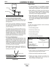
6. Loosen the drive roll set screw with the 5/64" (2.0
mm) hex wrench supplied.
7. Remove the drive roll, flip over and reinstall with the
.030/.035" (0.8/0.9 mm) groove (the larger groove)
closest to the gearbox.
8. Push a length of straightened welding wire through
the wire feeder guide tubes and adjust the position
of the drive roll so that the groove is centered on
the wire. Make certain the set screw is located on
the flat portion of the shaft and tighten.
CAUTION
3
2
1
Handymig 170i