


A-6
INSTALLATION
POWER WAVE® C300 CE
A-6
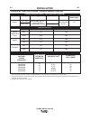
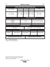
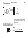
Function
12 pin connector
for Push pull
guns; foot pedal;
remote controls;
Hand –amptrols.
PIN
A
B
C
D
E
F
G
H
J
K
L
M
Wiring
CANL
CANH
Remote Pot Common
Remote Pot Wiper
Remote Pot +10VDC
ArcLink Peripheral Sense
Trigger
Trigger
Power Common
Power +
Motor Negative
Motor Positive
TABLE A.1
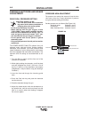
FIGURE A.3
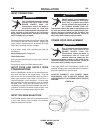
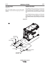
CABLE CONNECTION
There is one circular connection on the front of the
machine.
(See Figure A.2---Table A.1)
B
A
C
WORK
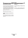
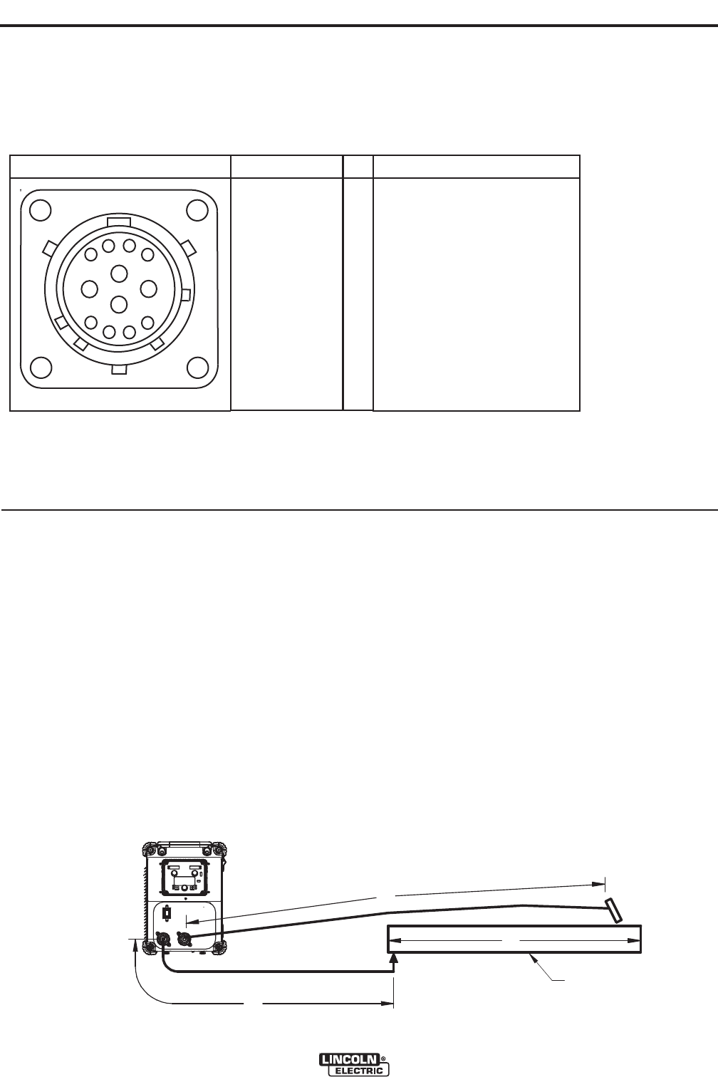
CABLE INDUCTANCE AND ITS
EFFECTS ON WELDING
Whenever possible always weld in a direction
away from the work (ground) connection.
Excessive cable inductance will cause the welding
performance to degrade. There are several factors
that contribute to the overall inductance of the cabling
system including cable size, and loop area. The loop
area is defined by the separation distance between
the electrode and work cables, and the overall welding
loop length. The welding loop length is defined as the
total of length of the electrode cable (A) + work cable
(B) + work path (C) (see Figure A.3).
To minimize inductance always use the appropriate
size cables, and whenever possible, run the electrode
and work cables in close proximity to one another to
minimize the loop area. Since the most significant fac-
tor in cable inductance is the welding loop length,
avoid excessive lengths and do not coil excess cable.
For long work piece lengths, a sliding ground should
be considered to keep the total welding loop length as
short as possible.
For additional Safety information regarding the elec-
trode and work cable set-up, See the standard
“SAFETY INFORMATION” located in the front of this
Instruction Manual.
FIGURE A.2