


B-23
OPERATION
B-23
POWER WAVE® C300 CE
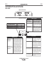
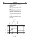
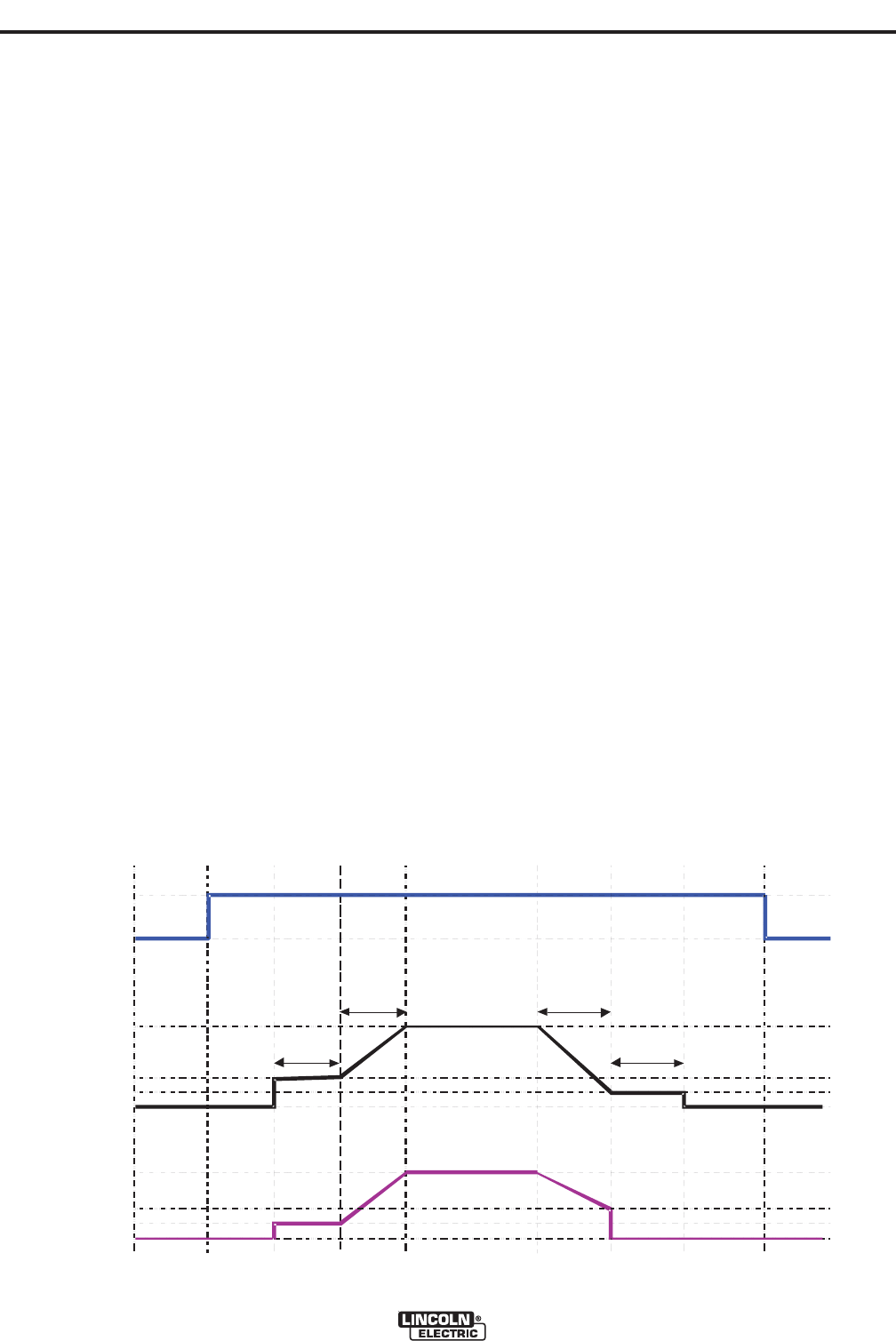
WELD:
After upslope, the power source output and the wire
feed speed continue at the weld settings.
CRATER & DOWNSLOPE:
As soon as the trigger is released, the wire feed
speed and power source output ramp to the crater
settings throughout the crater time. The time period of
ramping from the weld settings to the crater settings is
called DOWNSLOPE.
BURNBACK:
After the crater time expires, the wire feed speed is
turned OFF and the machine output continues for the
burnback time.
POSTFLOW:
Next, the machine output is turned OFF and shielding
gas continues until the post flow timer expires.
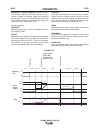
Shielding
Gas
Idle Preflow Strike Upslope Weld Bu rnback Postflow Idle
WFS
On
Off
Run-in
Off
Weld
Off
Weld
Arc Established
Trigger Pulled
Trigger Released
2 Step Trigger
Start = ON
Crater = ON
Burnback = ON
1.5 sec max.
Start
Start time
Burnback Time
Downslope
Crate r
Cr ater time
Power
Source
Output
Crater
FIGURE B.13
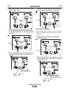
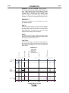
EXAMPLE 3 - 2 STEP TRIGGER: Customized Arc
Start, Crater and Arc End. Sometimes it is advanta-
geous to set specific arc start, crater and arc ending
parameters for the ideal weld. Many times when
welding aluminum crater control is necessary to make
a good weld. This is done by setting Start, Crater
and Burnback functions to desired values. (See
Figure B.13)
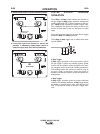
For this sequence,
PREFLOW:
Shielding gas begins to flow immediately when the
gun trigger is pulled.
RUN-IN:
After preflow time expires, the power source regulates
to the start output and wire is advanced towards the
work piece at the Run-In WFS. If an arc is not estab-
lished within 1.5 seconds, the power source output
and wire feed speed skips to the weld settings.
START & UPSLOPE:
As soon as the trigger is pulled, this starts preflow.
The Strike arc established, Start time, and Upslope
parameters are used at the beginning of the weld
sequence to establish a stable arc and provide a
smooth transition to the weld settings.