


A-9
INSTALLATION
POWER WAVE® C300 CE
A-9
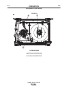
FEEDING ELECTRODE AND BRAKE
ADJUSTMENT
DRIVE ROLL PRESSURE SETTING
ELECTRIC SHOCK can kill.
• Turn the input power OFF at the weld-
ing power source before installation or
changing drive rolls and/or guides.
• Do not touch electrically live parts.
• When feeding with the gun trigger, unless
“COLD FEED” trigger mode is selected, the elec-
trode and drive mechanism are always “HOT” to
work and ground and could remain “HOT” sev-
eral seconds after the gun trigger is released.
• Do not operate with covers, panels or guards
removed or open
• Only qualified personnel should perform mainte-
nance work.
------------------------------------------------------------------------
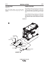
The POWER WAVE® C300 CEʼs optimum drive roll
pressure varies with type of wire, surface condition,
lubrication, and hardness. Too much pressure could
cause birdnesting”, but too little pressure could cause
wire feed slippage with load and/or acceleration. The
optimum drive roll setting can be determined as fol-
lows:
1.
Turn the Reel or spool until the free end of the
electrode is accessible.
2. While tightly holding the electrode, cut off the bent
end and straighten the first 6" (150 mm). Cut off
the first 1" (25 mm). (If the electrode is not properly
straightened, it may not feed or may jam causing a
"birdnest".)
3. Insert the free end through the incoming guide
tube.
4. Press the Cold Inch key and push the electrode
into the drive roll.
5. Feed the electrode through the gun.
6. Adjust the brake tension with the thumbscrew on
the spindle hub, until the reel turns freely but with
little or no overrun when wire feeding is stopped.
Do not over tighten.
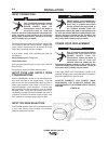
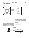
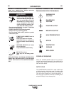
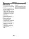
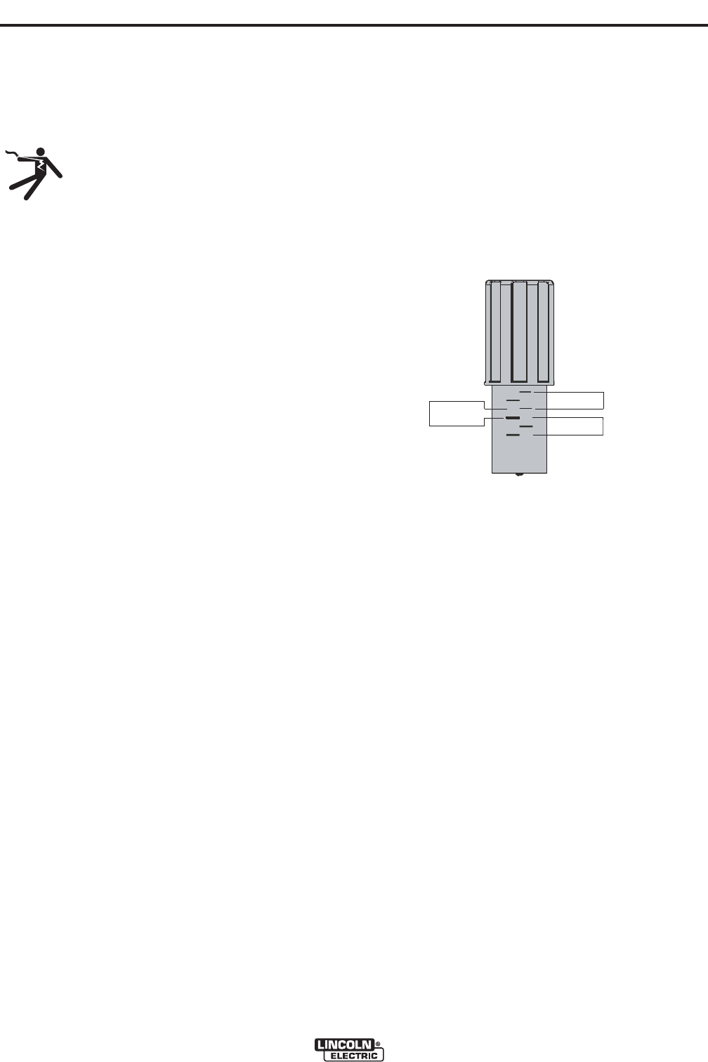
PRESSURE ARM ADJUSTMENT
The pressure arm controls the amount of force the drive
rolls exert on the wire. Proper adjustment of pressure
arm gives the best welding performance.
Set the pressure arm as follows (See Figure A.6):
Aluminum wires between 1 and 3
Cored wires between 3 and 4
Steel, Stainless wires between 4 and 6
FIGURE A.6
ALUMINUM
FLUX CORE
ARC WELDING
GAS METAL
ARC WELDING
6
1
3
2
5
4
Aluminum wires
Cored wires
Steel, Stainless wires