


B-11
OPERATION
B-11
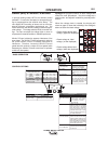
GMAW (MIG) SYNERGIC WELDING
In synergic welding modes, WFS is the dominant control
parameter. For each wire feed speed, a corresponding volt-
age is programmed into the machine at the factory. The
user adjusts WFS according to factors such as wire size,
material thickness, penetration requirements, etc. The
Power Wave then uses the WFS setting to select the appro-
priate voltage. The voltage selected will be a nominal volt-
age. The user can adjust the voltage higher or lower to
compensate for material condition or individual preference.
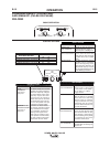
UltimArc™Control, adjusts the apparent inductance of the
wave shape. The UltimArc™Control adjustment is similar to
the “pinch” function in that it is inversely proportional to
inductance. Therefore, increasing UltimArc™Control
greater than 0.0 results in a crisper arc (more spatter) while
decreasing the UltimArc™Control to less than 0.0 provides
a softer arc (less spatter).
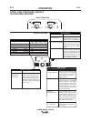
POWER WAVE® C300 CE
EFFECT / RANGE
PINCH EFFECT
(-10.0 to +10.0)
0 to 120.0 Seconds
0 to 0.25 Seconds
0 to 10 Seconds
DESCRIPTION
-
EFFECT
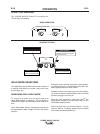
Preflow Time:
0 To 10 Seconds
Run-in WFS:
Off, 0.76 to 3.81 m/min.
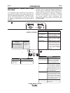
Start Procedure
DESCRIPTION
Adjusts the time
that shielding
gas
flows
after the
trigger
is
pulled and
prior to feeding.
Run-In sets the wire feed
speed from the time the trigger
is pulled until an arc is estab-
lished.
The Start Procedure controls
the WFS, Volts at a specified
time at the beginning of the
weld. During the start time, the
machine will ramp up or down
from the Start Procedure to the
preset Welding Procedure.
EFFECT
DESCRIPTION
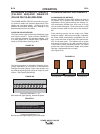
Steel
Steel
Stainless
Stainless
Aluminum 4043
Aluminum 5356
ELECTRODE AND GAS
CO
2
Ar(Mix)
Ar(Mix)
Ar/He/CO
2
Ar
Ar
WIRE SIZE
.08 .09 1.0 1.2
93
14 10 20
94 15 11 21
61 29 31 41
63 --- --- ---
--- --- --- 71
--- --- 151 75
WELD MODE
UltimArc™ Control
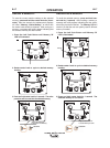
END OPTIONS
START OPTIONS
Pinch controls the arc characte-
-ristics when short-arc welding.
Spot Timer
Adjust the time welding will
continue even if the trigger
is still pulled. This option
has no effect in 4-Step
Trigger Mode.
Crater Procedure
Crater Procedure controls the
WFS and Volts for a specified
time at the end of the weld
after the trigger is released.
During the Crater time, the
machine will ramp up or down
from the Weld Procedure to
the Crater Procedure.
Burnback:
The burnback time is the
amount of time that the weld
output continues after the wire
stops feeding. It prevents the
wire from sticking in the puddle
and prepares the end of the
wire for the next arc start.
Postflow Time
Adjusts the time that shielding
gas flows after the welding out-
put turns off.
4.50
20.0
LESS
AMPS
MORE
AMPS
OUTPUT
OFF
OUTPUT
ON
+
+
A
V
STEEL 1.0mm
CV CO2
10
4T
M
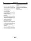
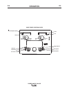
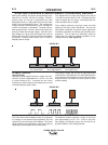
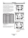
Synergic CV programs feature an ideal voltage best
suited for most procedures. Use this voltage as a
starting point and adjust if needed for personal prefer-
ences.
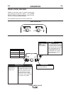
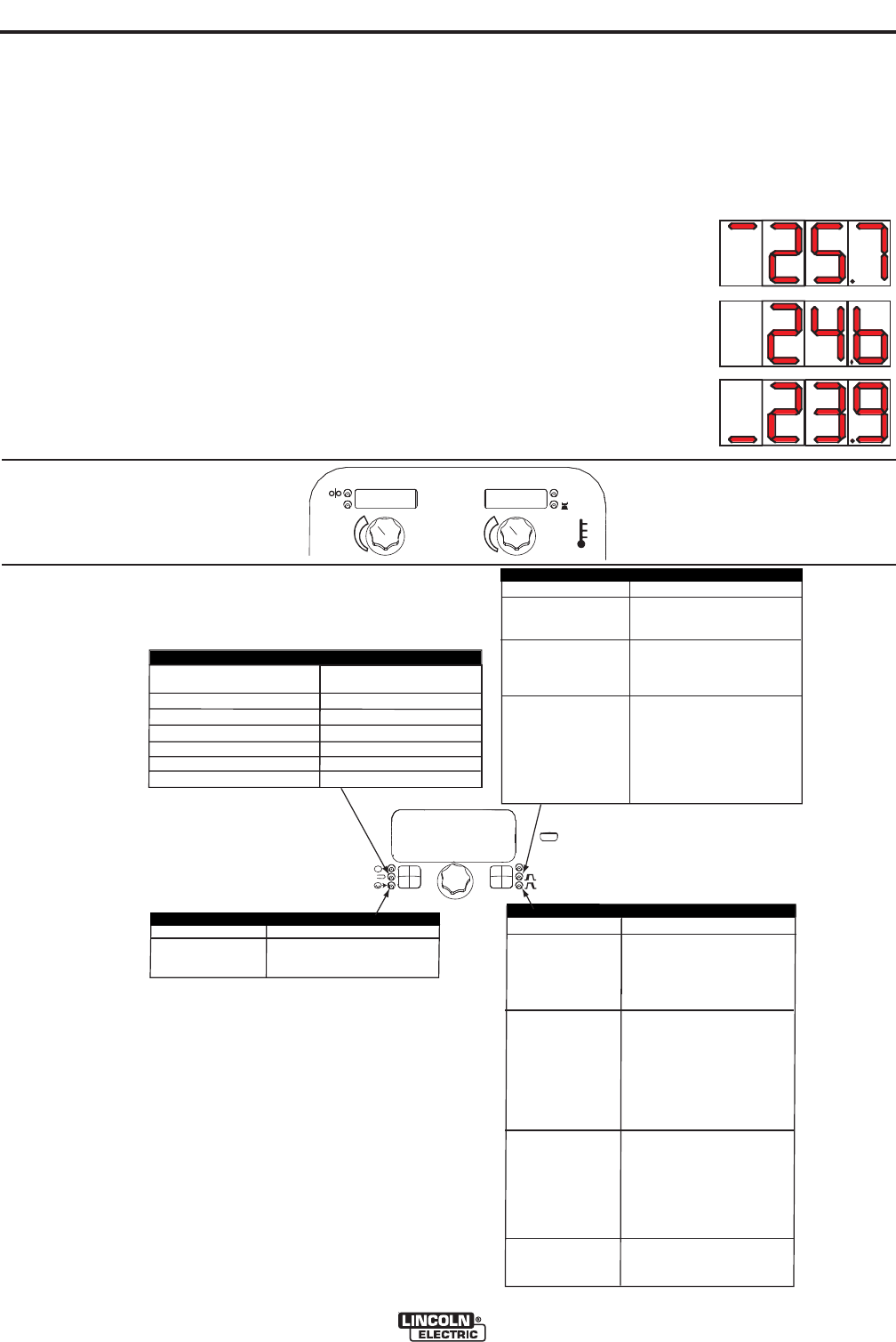
When the voltage knob is rotated, the display will
show an upper or lower bar indicating if the voltage is
above or below the ideal voltage.
• Preset voltage above ideal
voltage. (upper bar displayed)
• Preset voltage at ideal
voltage. (no bar displayed)
• Preset voltage below ideal
voltage. (lower bar displayed)
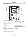
BASIC OPERATION
CONTROL OPTIONS