


B-4
OPERATION
B-4
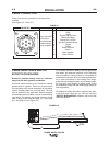
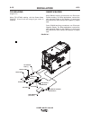
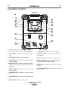
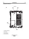
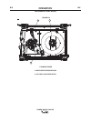
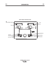
CASE FRONT CONTROLS
All operator controls and adjustments are located on
the case front of the Power Wave. (See Figure B.1)
1. LEFT DISPLAY- Shows wire feed speed or amper-
age,
2. LEFT KNOB- Adjusts value in left display.
3. MAIN DISPLAY- Shows detailed welding and diag-
nostic information.
4. LEFT BUTTON- Changes the Main display to
show the Weld Mode or UltimArc™ Control or
Memories.
5. ON/OFF SWITCH- Controls power to the Power
Wave C300CE.
6. + OUTPUT STUD- Connection for electrode posi-
tive.
7. - OUTPUT STUD- Connection for electrode nega-
tive.
8. RIGHT DISPLAY- Shows voltage or trim.
9. RIGHT KNOB- Adjusts value in right display.
10. THERMAL LIGHT- Indicates when machine has
thermal fault.
11. SET-UP- Lights when machine is in set-up mode,
12. RIGHT BUTTON- Changes the Main display to
arc start, arc end and trigger options.
13. MAIN KNOB- Changes the values on the Main
display.
14. 12 PIN CONNECTOR- Connection for push pull
guns, remotes.
POWER WAVE® C300 CE
1
2
3
4
5
6
7
8
9
10
11
12
13
14
1
2
3
4
5
6
7
8
9
10
11
12
13
14
FIGURE B.1