


B-12
OPERATION
B-12
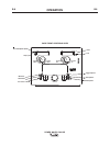
POWER WAVE® C300 CE
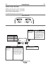
STEEL AND STAINLESS SYNERGIC GMAW-P (PULSED MIG) WELDING
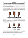
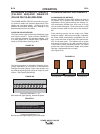
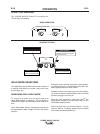
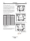
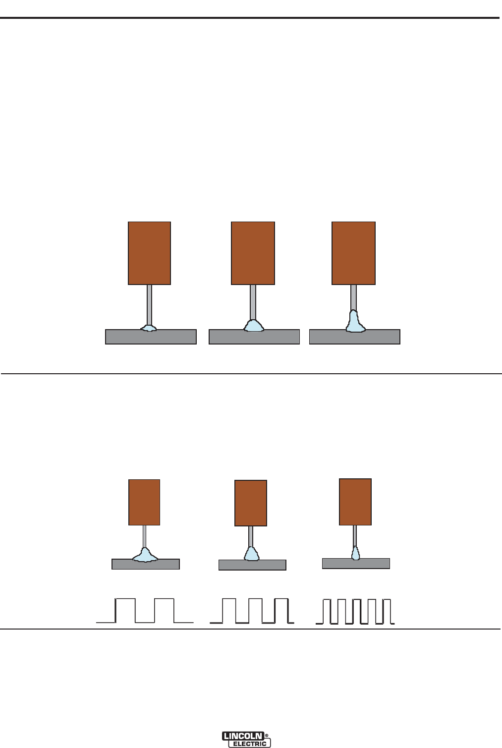
Trim .50
Arc Len
g
th Short
Trim 1.00
Arc Len
g
th Medium
Trim 1.50
Arc Length Long
Trim .50
Arc Len
g
th Short
Trim 1.00
Arc Len
g
th Medium
Trim 1.50
Arc Length Long
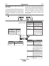
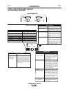
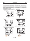
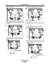
OFF
Medium Frequency and Width
+10.0
High Frequency, Focused
UltimArc™ Control -10.0
Low Frequency, Wide
UltimArc™ Control
UltimArc™ Control
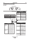
OFF
Medium Frequency and Width
+10.0
High Frequency, Focused
UltimArc™ Control -10.0
Low Frequency, Wide
UltimArc™ Control
UltimArc™ Control
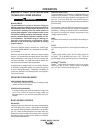
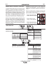
When pulse welding, the power source primarily regu-
lates the arc current, not the arc voltage. During a
pulsing cycle, arc current is regulated from a low
background level to a high peak level and then back
down to the low background level. The average arc
voltage increases and decreases as the average arc
current is increased or decreased. The peak current,
back ground current, rise time, fall time and pulse fre-
quency all affect the average voltage. Since the aver-
age voltage for a given wire feed speed can only be
determined when all the pulsing waveform parameters
are known, a unitless value called “trim” is used for
adjusting the arc length.
ULTIMARC™CONTROL
(See Figure B.6)
UltimArc™Control adjusts the focus or shape of the arc.
UltimArc™Control is adjustable from -10.0 to +10.0 with
a nominal setting of 0.0. Increasing the arc control
increases the pulse frequency and background current
while decreasing the peak current.
The Power Wave utilizes adaptive control to compensate
for changes in the electrical stick-out(distance from the
contact tip to the work piece) while welding. The Power
Wave waveforms are optimized for a 5/8” to 3/4” stick out
depending on the wire type and wire feed speed.
This results in a tight, stiff arc used for high speed sheet
metal welding. Decreasing the arc control decreases the
pulse frequency and background current while increasing
the peak current. This results in a soft arc good for out of
position welding.
The adaptive behavior supports a range of stick outs
from approximately 1/2” to 1-1/4”. At low or high wire
feed speeds, the adaptive range may be less due to
physical limitations of the welding process.
Trim adjusts the arc length and ranges from 0.50 to
1.50 with a nominal value of 1.00. Increasing the trim
value increases the arc length. Decreasing the trim
value decreases the arc length.
Pulse welding modes are synergic; using wire feed
speed as the main control parameter. As the wire
feed speed is adjusted, the power source adjusts the
waveform parameters to maintain good welding char-
acteristics. Trim is used as a secondary control to
change the arc length for material conditions or indi-
vidual preference. (See
Figure B.5)
FIGURE B.5
FIGURE B.6