%*+##+ &%
'&.)S$* %#. ))
*+0'),+ &%
#+) *&" 53@
=;>>
Q&@>KCG3>;8;76B7DEA@@7>E:AG>6
B7D8AD?F:;E;@EF3>>3F;A@
Q+GD@A88F:7;@BGFBAI7DFAF:7BAI7DEAGD573F
F:76;E5A@@75FEI;F5:AD8GE74AJ478AD7IAD=
;@9A@F:;E7CG;B?7@F+GD@A88F:7;@BGFBAI7D
FA3@KAF:7D7CG;B?7@F5A@@75F76FAF:7I7>6
;@9EKEF7?3FF:76;E5A@@75FEI;F5:AD8GE7
4AJ478AD7IAD=;@9A@F:;E7CG;B?7@F
QA@AFFAG5:7>75FD;53>>K:AFB3DFE
---------------------------------------------------------------------------------------
.:7@GE;@93@;@H7DF7DFKB7BAI7DEAGD57>;=7F:7
'AI7D.3H7EGE7F:7>3D97EFI7>6;@97>75FDA67
3@6IAD=534>7EF:3F3D7BD35F;53>F>73EF
5ABB7DI;D77H7@;8F:73H7D397AGFBGF5GDD7@F
IAG>6@AF@AD?3>>KD7CG;D7;F.:7@BG>E;@9F:7
BG>E75GDD7@F53@D735:H7DK:;9:>7H7>E-A>F397
6DABE53@475A?77J57EE;H7>736;@9FABAAD
I7>6;@95:3D35F7D;EF;5E;8G@67DE;L76I7>6;@9
534>7E3D7GE76
------------------------------------------------------------------------
.##* 1*
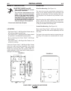
Table A.2 has the copper cable sizes recommended
for different currents and duty cycles. Lengths stipu-
lated are the distance from the welder to work and
back to the welder again. Cable sizes are increased
for greater lengths primarily for the purpose of mini-
mizing voltage in the welding circuit.
#+)&#
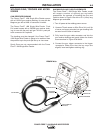
Most welding applications run with the electrode being
positive (+). For those applications, connect the elec-
trode cable between the wire feeder and the positive
(+) output stud on the power source. Connect the lug
at the other end of the electrode cable to the wire
drive feed plate. Be sure the connection to the feed
plate makes tight metal-to-metal electrical contact.
The electrode cable should be sized according to the
specifications given in the work cable connections
Table A.1. Connect a work lead from the negative (-)
power source output stud to the work piece. The work
piece connection must be firm and secure, especially
if pulse welding is planned.
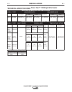
.##* 1 %
Minimum work and electrode cables sizes are as follows:
+#
GDD7@FGFKK5>7
$ % $,$&'')
.&)"#* 1.
Up To-100 Ft. Length (30 m)
400 Amps 2/0 (67 mm2)
500 Amps 3/0 (85 mm2)
600 Amps 3/0 (85 mm2)
NOTE: K1796 coaxial welding cable is recommended
to reduce the cable inductance in long distance Pulse
or STT applications up to 300 amps.
.##&%%+ &%
Connect a work lead of sufficient size and length (Per
Table A.1) between the proper output terminal on the
power source and the work. Be sure the connection to
the work makes tight metal-to-metal electrical contact.
To avoid interference problems with other equipment
and to achieve the best possible operation, route all
cables directly to the work or wire feeder. Avoid
excessive lengths and do not coil excess cable.
?B7D7E
'7D57@F
GFK
K5>7
FAF
FA?
FAF
FA?
FAF
FA?
FAF
FA?
FAF
FA?
)&$$%#* 1*),)&-)&''))+P
#* 1*&)&$ %#%+*&#+)&%.&)"#*
+#
** Tabled values are for operation at ambient temperatures of 40°C and below. Applications above 40°C may require cables larger than
recommended, or cables rated higher than 75°C.


