


&')+ &%
*++,*#
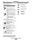
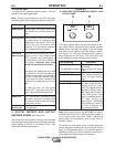
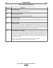
The status LED indicates system status. Normal
operation is a steady green light.
%AF7 During normal power-up, the LED may flash
red and/or green as the equipment performs self tests.
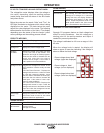
#5A@6;F;A@ Definition
*F736K9D77@ System okay. The power source and
wire feeder are communicating nor-
mally.
>;@=;@99D77@ Occurs during a reset and indicates
the power source is identifying each
component in the system. This is nor-
mal for the first 10 seconds after
power-up, or if the system configura-
tion is changed during operation.
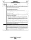
>F7D@3F;@9 Non-recoverable system fault. If the
9D77@3@6D76 power source or wire feeder status
LED is flashing any combination of
red and green, errors are present in
the system. )736F:77DDAD5A67
478AD7F:7?35:;@7;EFGD@76A88
Instructions for reading the error code
are detailed in the Service Manual.
Individual code digits are flashed in
red with a long pause between digits.
If more than one code is present, the
codes will be separated by a green
light.
To clear the error, turn the power
source OFF, and then back ON to
reset. See troubleshooting section.
*F736KD76 Non recoverable hardware fault.
Generally indicates a problem with
the cables connecting the wire feeder
to the power source.
>;@=;@9D76 Not applicable.
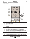
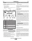
+# $+)* % &,+',+
%&)"%&*
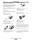
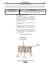
(See Figure B.2)
The primary weld procedure settings are controlled
and displayed using digital meters and output encoder
knobs located at the top of the Power Feed™ 10M
Single Wire Feeder control panel.
'&.)S$* %#. ))
,)
. )*'$$+) *'#0%
&,+',+"%&
This meter displays either the wire feed speed or cur-
rent value (Amps) depending upon welding process
(Mode) being used and the status of the wire feeder
and power source. Written below the display is "WFS"
and "Amps". An LED light illuminates which value is
being displayed on the meter. The knob below the
meter adjusts the value displayed on the meters.
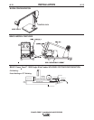
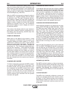
'D;ADFA.7>6;@9 7E5D;BF;A@
CV Welding Processes Meter displays the preset
WFS value.
CC Welding Processes Meter displays the preset
Amps.
GD;@9.7>6;@9
An Weld Processes Meter displays displays the
actual average welding
Amps.
8F7D.7>6;@9
An Weld Processes The meter holds the actual
current value for 5 sec-
onds. The display blinks to
indicate the Power Feed™
10M Single Wire Feeder is
in the "Hold" period. If the
output is adjusted while in
the "Hold" period, the
Power Feed™ 10M Single
Wire Feeder will revert to
the "Prior to welding" dis-
play described above.
%AF7 If the output knob for the WFS/AMPS is adjust-
ed while the Power Feed™ 10M Single Wire Feeder is
in the “Hold” period, the Power Feed™ 10M Single
Wire Feeder will immediately revert to the “Prior to
Welding” display.
The default wire feed speed units are inches/minute and
can be changed to meters/minute by entering the "Set-up
Menu" in this Operation Section. The wire feed speed is
calibrated to within ±2%. Refer to the power source man-
ual for calibration specifications of the ammeter.
400
263
WFS AMPS
VOLTS TRIM
A
B
400
263
WFS AMPS
VOLTS TRIM
A
B