


Electrode
Work
Work
Power Source
Work
Electrode
Wire Feeder
Electrode
Work
Coaxial Weld Cable
Electrode
Work
Work
Power Source
Work
Electrode
Wire Feeder
Electrode
Work
Coaxial Weld Cable
% %#+)&'&#) +0
*++ %
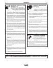
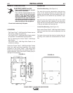
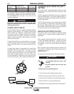
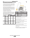
The Power Feed™ 10M Single Wire Feeder is preset
at the factory for Electrode Positive welding. (See
Figure A.3)
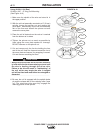
NOTE: Changing this DIP Switch does not change the
actual welding polarity. The actual welding polarity is
changed by reversing the welding cables at the power
source output studs.
This DIP Switch setting must coincide with the polarity
you are setting up to weld with for the feeder to oper-
ate correctly. Operating the Power Feed™ 10M Single
Wire Feeder with the DIP switch in the wrong position
will cause very erratic weld characteristics.
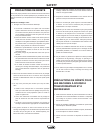
%+ -#+)&'&#) +0
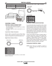
This options allows for the setting of negative polarity
sensing when a negative polarity welding process is
performed.
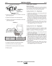
When negative electrode polarity is required, such as
in some Innershield applications, reverse the output
connections at the power source (electrode cable to
the negative (-) stud, and work cable to the positive
(+) stud).
When operating with electrode polarity negative the
Power Feed™ 10M Single Wire Feeder must be set to
recognize this set-up.
(See Figure A.3)
To change the electrode polarity DIP Switch setting:
6+*+00+1 %"(" 0.& ((5(&2",.0/
+."(" 0.+!"/3&0%5+1./'&*+.3"0
(+0%&*$
6*/1(0"5+1./"(##.+)0%"3+.'*!
$.+1*!
6(35/3".!.5&*/1(0&*$$(+2"/
----------------------------------------------------------------------------------------
1. Turn off power at the welding power source.
2. Remove the rear access panel on the wire drive.
3. Locate the DIP switches on the Wire Drive Board.
4. Set DIP switch #7 to the desired polarity.
5. Reinstall the rear access panel and restore power.
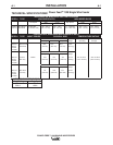
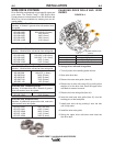
.)% %
%*+##+ &%
'&.)S$* %#. ))
AD>75FDA67 A@@75FF:7 A@@75FF:7
'A>3D;FK >75FDA67>736FA IAD=>736FA
Positive Positive Stud Negative
Negative Negative Stud Positive Stud
For additional Safety information regarding the elec-
trode and work cable set-up, See the standard "SAFE-
TY INFORMATION" located in the front of the
Instruction Manuals.
J57EE;H7HA>F3976DABE53GE764KBAADIAD=
B;7575A@@75F;A@EA8F7@D7EG>F;@G@E3F;E835FADK
I7>6;@9B7D8AD?3@57
---------------------------------------------------------------------------------------
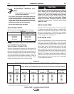
&/ #.##*
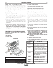
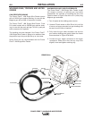
Coaxial welding cables are specially designed welding
cables for pulse welding or STT welding. Coaxial weld
cables feature low inductance, allowing fast changes
in the weld current. Regular cables have a higher
inductance which may distort the pulse or STT wave
shape. Inductance becomes more severe as the weld
cables become longer.
Coaxial weld cables are recommended for all pulse
and STT welding, especially when the total weld cable
length (electrode cable + work cable) exceeds 50 feet
(7.6m)
A coaxial weld cable is constructed by 8 small leads
wrapped around one large lead. The large inner lead
connects to the electrode stud on the power source
and the electrode connection on the wire feeder. The
small leads combine together to form the work lead,
one end attached to the power source and the other
end to the work piece.
(See Coaxial weld Cable below.)