


F-49
TROUBLESHOOTING & REPAIR
F-49
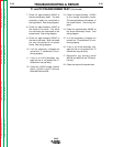
TEST PROCEDURE
1. Remove the wire feed motor connec-
tor from the NA-5 control box.
2. Using the ohmmeter, measure the
resistances per the table below. Also
see Figure F.5.
3. If the motor resistance test is good,
proceed to the
Motor Applied Voltage
Test
.
MOTOR APPLIED
VOLTAGE TEST
1. Carefully connect the isolated 120
VDC supply (SUPPLY TURNED
OFF) to pins C and D on the motor
connector.
2. Carefully connect the variable 0 to 90
VDC supply (SUPPLY TURNED
OFF) to pins A and B on the motor
connector. (See Table F.1.)
3. Apply field voltage first (pins C and
D) to the motor. Then, slowly apply
the armature voltage to pins A and B.
(See Table F.1).
4. The motor should run, and the speed
should vary with changes to the
armature voltage.
5. If the motor does NOT run and
change speed correctly, the motor or
gear box may be faulty.
6. To stop the motor, REMOVE THE
ARMATURE VOLTAGE FIRST (pins
A and B).
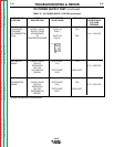
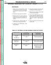
WIRE FEED DRIVE MOTOR TEST (Continued)
NA-5
TEST POINTS RESISTANCE DC VOLTAGE
Lead #539 to lead #541 4 to 5 ohms 0 to 90 VDC
armature
Lead #626 to lead #627 750 to 850 ohms 90 to 120 VDC
field winding
All leads 500,000 ohms NONE
to min.
motor shell
(Except lead #67)
Lead #67 to motor zero ohms Not Applicable
shell
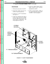
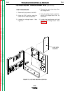
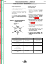
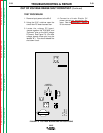
FIGURE F.5 WIRE FEED DRIVE MOTOR
CONNECTOR PINS.
F
A
B
C
D
E
#541
#539
#67
#627
#626
MOTOR
CONNECTOR
PINS
Return to Section TOC Return to Section TOC Return to Section TOC Return to Section TOC
Return to Master TOC Return to Master TOC Return to Master TOC Return to Master TOC