


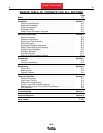
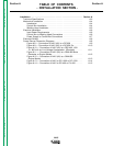

TABLE OF CONTENTS
- INSTALLATION SECTION -
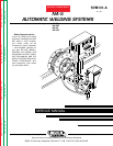
NA-5
Installation . . . . . . . . . . . . . . . . . . . . . . . . . . . . . . . . . . . . . . . . . . . . . Section A
Technical Specifications . . . . . . . . . . . . . . . . . . . . . . . . . . . . . . . . . A-2
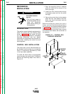
Mechanical Installation . . . . . . . . . . . . . . . . . . . . . . . . . . . . . . . . . . A-4
Introduction . . . . . . . . . . . . . . . . . . . . . . . . . . . . . . . . . . . . . . . A-4
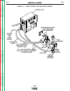
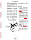
Control Box Installation . . . . . . . . . . . . . . . . . . . . . . . . . . . . . . . A-4
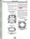
Welding Head Installation . . . . . . . . . . . . . . . . . . . . . . . . . . . . . A-5
Electrical Installation . . . . . . . . . . . . . . . . . . . . . . . . . . . . . . . . . . . . A-6
Input Power Requirements . . . . . . . . . . . . . . . . . . . . . . . . . . . . A-6
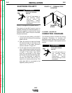
Control Box to Welding Head Connections . . . . . . . . . . . . . . . . . A-6
Power Supply to Control Box Connections . . . . . . . . . . . . . . . . . A-7
Electrode Polarity . . . . . . . . . . . . . . . . . . . . . . . . . . . . . . . . . . . . . . A-8
Power Source Connection Diagrams . . . . . . . . . . . . . . . . . . . . . . . . A-8
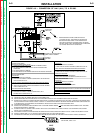
Figure A.8 — Connection of NA-5 (All) to a DC-600 . . . . . . . . . . A-9
Figure A.9 — Connection of NA-5 (All) to a DC-650 Pro . . . . . . . A-10
Figure A.10 — Connection of NA-5 (All) to a R3S-400, -600
or -800 with no Line Voltage Compensator (Obsolete) . . . . . . A-11
Figure A.11 — Connection of NA-5 (All) to a SAM-400 Motor
Generator or Engine Welder . . . . . . . . . . . . . . . . . . . . . . . . . . A-12
Figure A.12 — Connection of NA-5 (All) to a SAM-650
Engine Welder . . . . . . . . . . . . . . . . . . . . . . . . . . . . . . . . . . . . A-13
Figure A.13 — Connection of NA-5 to DC-1000 or DC-1500 . . . . A-14
Figure A.14 — Connection of NA-5 to DC-400 or CV-400 . . . . . . A-15
Section ASection A
Return to Master TOC Return to Master TOC Return to Master TOC Return to Master TOC