


F-56
TROUBLESHOOTING & REPAIR
F-56
PROCEDURE
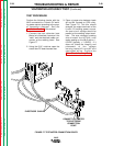
1. Remove input power to the NA-5.
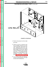
2. Using the 5/16" nutdriver open the
control box PC board access door.
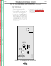
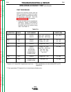
3. Locate leads #510A, #525A and
#555 on the control board.
4. Apply 115VAC to the NA-5 wire
feeder at the correct pins. See
wiring diagram.
5. Check leads #525A(+) to #510A(-)
for the presence of 15VDC. This is
the supply voltage from the control
PC board to the tach PC board. If
the voltage is present, proceed to
the next step. If the voltage is miss-
ing check the associated wiring and
then perform the
DC Power Supply
Test
.
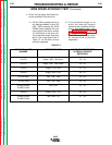
6. With the motor running (activate
either inch switches or the start
switch) and check leads #555(+) to
#510A(-) for the presence of
between 4.5 - 10.5VDC. (The motor
must be running.) This is the feed-
back voltage from the tach PC board
to the control PC board. This volt-
age is dependent upon motor speed.
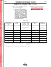
7. If the feedback voltage is missing or
does not vary with motor speed, the
tach PC board may be faulty. Also
check for loose or faulty connec-
tions.
8. After the completion of the tests
remove the 115VAC power and
close and secure the access door.
TACH BOARD FEEDBACK TEST (Continued)
NA-5
Return to Section TOC Return to Section TOC Return to Section TOC Return to Section TOC
Return to Master TOC Return to Master TOC Return to Master TOC Return to Master TOC