


OPERATING INSTRUCTIONS
B-7B-7
NA-5
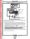
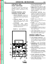
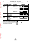
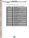
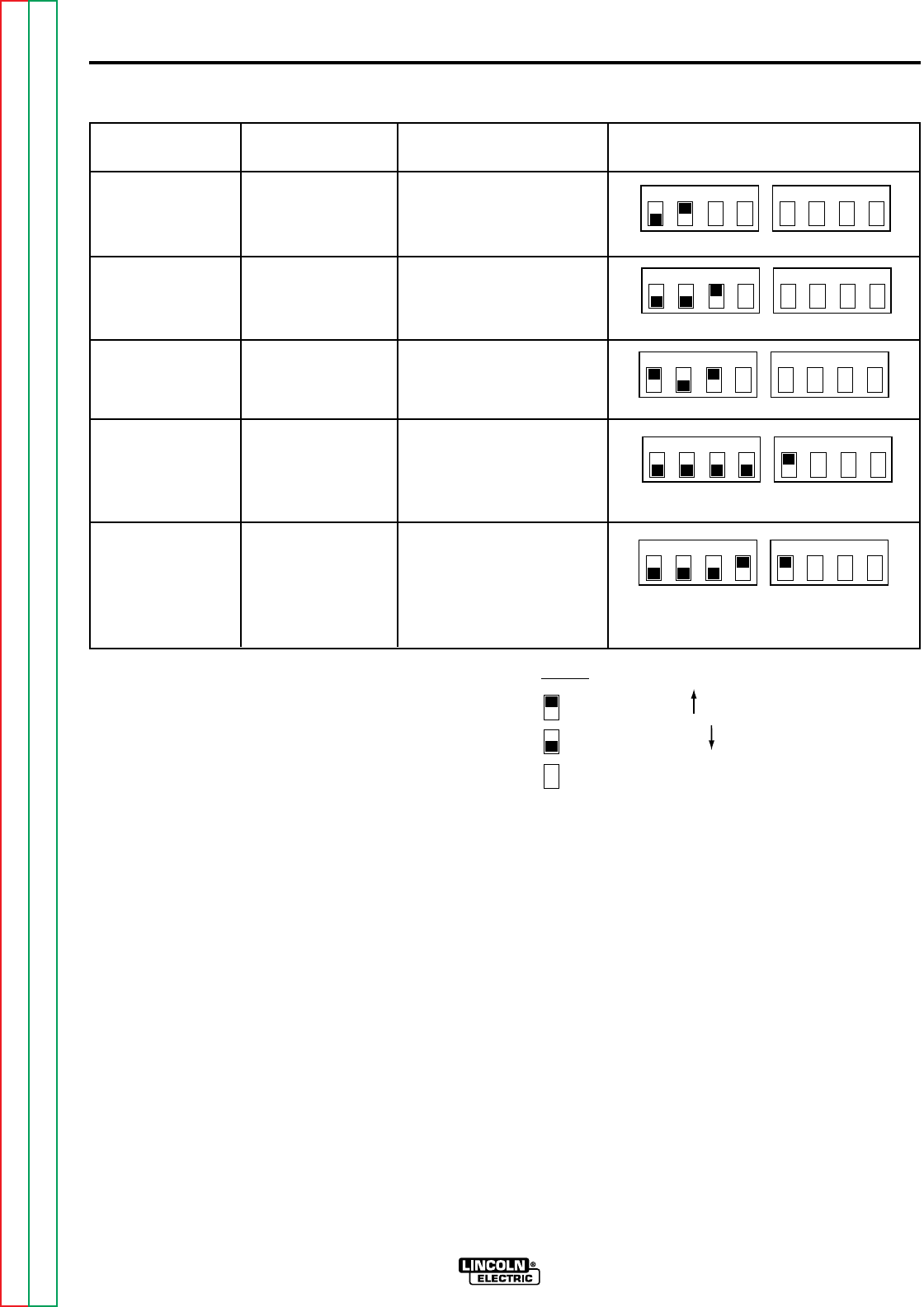
Travel Starts Travel Stops Older Models Newer Models*
With “Start” With “Stop” Lead #691 to Pin 6
Button Button Lead #692 to Pin 5
With Arc Striking With Arc Stopping Lead #691 to Pin 6
Lead #692 to Pin 7
With Arc Striking With Stop Button Lead #691 to Pin 5
Lead #692 to Pin 7
With “Start” With End Crater Lead #691 to Pin 6
Button Fill Time (With Lead #692 to Pin 9
optional procedure
module installed in
crater receptacle
1
)
With “Start” After Burnback Lead #691 to Pin 6
Button Time (with Lead #692 to Pin 8
optional procedure
module installed
in crater
receptacle
1
)
1234 1234
Switch #1 Switch #2
1234 1234
Switch #1 Switch #2
1234 1234
Switch #1 Switch #2
1234 1234
Switch #1 Switch #2
TABLE B.1 – TRAVEL SEQUENCE LEAD AND SWITCH POSITIONS.
1234 1234
Switch #1 Switch #2
*NOTE:
Indicates switch in up position
Indicates switch in down position
Indicates switch position does not matter
1
If the optional procedure module is installed in the crater receptacle,
DIP switch position 1 on switch #2 should be in the UP position as
shown. Additionally, remove 583C to 584C jumper plug from the pro
cedure board. If the procedure module is not installed, the switch
should be in the down position and the 583C to 584C jumper plug
should be reinstalled on the procedure board.
Return to Section TOC Return to Section TOC Return to Section TOC Return to Section TOC
Return to Master TOC Return to Master TOC Return to Master TOC Return to Master TOC