


F-66
TROUBLESHOOTING & REPAIR
F-66
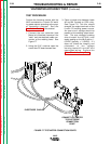
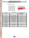
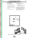
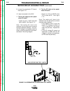
6. Test for DC volts on the voltmeter
PC board.
• Check for 4.75 to 5.25VDC from
TP5 to lead #510C. See Figure
F.9
Note: The coating will have to be
removed from the test points to ensure
accurate voltmeter readings.
• If the display is NOT lit and the
correct DC voltage is present at
TP5 to lead #510C, the digital
meter may be faulty. Replace the
meter.
• If the AC voltage IS present at
leads #601 to #602 and the DC
voltage is missing, the voltmeter
PC board may be faulty.
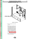
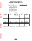
7. Test Digital Voltmeter Accuracy
• Use a test meter with at least 3-
1/2 digits and +/- 0.5% accuracy.
• Connect the + probe to TP4 and
the - probe to lead 510C. Do NOT
disconnect plug.
Note: The coating will have to be
removed from the test points to ensure
accurate meter readings.
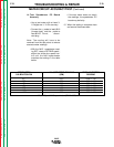
• With the NA-5 voltmeter reading
SET values of STRIKE voltage,
adjust the strike voltage control
until the test meter matches the
settings in the table below.
• If the NA-5 digital voltmeter does
not match the readings, the digital
meter may be faulty.
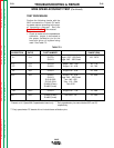
METER CIRCUIT ACCURACY TEST (Continued)
NA-5
NA-5 SET VOLTS READING TEST VOLTMETER READING
15.0VDC .150 +/- .004VDC
30.0VDC .300 +/- .004VDC
60.0VDC .600 +/- .006 VDC
Return to Section TOC Return to Section TOC Return to Section TOC Return to Section TOC
Return to Master TOC Return to Master TOC Return to Master TOC Return to Master TOC