


F-43
TROUBLESHOOTING & REPAIR
F-43
PROCEDURE
1. Remove all input power to the NA-5.
2. Using 5/16" nutdriver open the con-
trol box PC board access door.
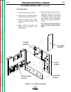
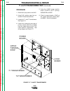
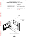
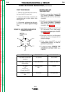
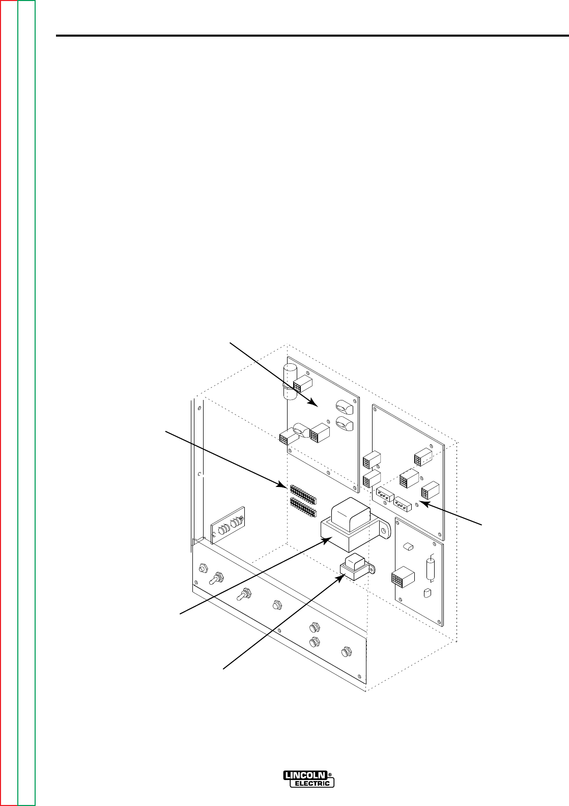
3. Locate the T1 and T2 transformers.
See Figure F.2
4. Locate and remove the two sets of
primary leads (#531B and #532)
from the upper terminal strip TS2.
Label leads for reassembly. See
wiring diagram and Figure F.2
5. Using the 115VAC supply carefully
apply 115VAC to the T1 primary
leads #531B and #532.
6. Check for approximately 10VAC at
the yellow secondary leads (#601
and #602). See wiring diagram.
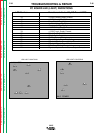
T1 and T2 TRANSFORMER TEST (Continued)
NA-5
FIGURE F.2 T1 AND T2 TRANSFORMERS
POWER
BOARD
LOGIC
BOARD
UPPER
TERMINAL
STRIP
T1 TRANSFORMER
T2 TRANSFORMER
Return to Section TOC Return to Section TOC Return to Section TOC Return to Section TOC
Return to Master TOC Return to Master TOC Return to Master TOC Return to Master TOC