


E-4
THEORY OF OPERATION
E-4
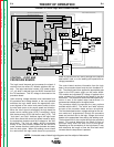
CONTROL, LOGIC AND
PROCEDURE BOARDS
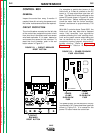
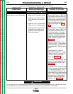
The logic board interprets and processes the signals it
receives from the various PC boards, switches and con-
trols. The logic board also houses a DC power supply
(+5 -10) which is derived from the 22VAC received from
the T2 transformer. This DC voltage is also used on the
procedure board.
Upon receiving voltage reference level commands from
the procedure and voltage boards, or the user-operated
switches, the logic board sends the appropriate com-
mand signals to the control and power boards to drive
the wire feed motor to the proper speed and direction.
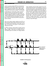
When the "start" signal is received by the logic board the
power source contact relay (3CR) is energized along
with the travel relay (2CR) and the flux relay (1CR). The
"inch down" and "stop" switches signal the logic board
which then directs the control and power boards to apply
the appropriate armature and field voltages to the wire
drive motor. The "inch up" switch, which is connected
directly to the control board, dictates that the wire drive
motor reverse direction, backing the electrode wire away
from the work piece. When the welding current closes
the reed switch the logic board directs the procedure
board to proceed from the "strike" settings to the optional
start board if used, or to the welding wire speed and arc
voltage parameters.
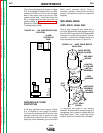
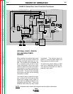
The control board receives information from the logic
board, the procedure board and the tach feedback cir-
cuit. The control board then applies the appropriate gate
signal to the SCR power supply on the power board.
This variable and regulated DC voltage is applied to the
motor armature thus controlling the speed of the wire
feed motor. The preset and actual wire feed speed infor-
mation is sent to the speed meter board where it is
processed and displayed on the digital meter.
The procedure board incorporates the many options
available with the NA-5. The "strike" and "weld" controls
are part of the procedure board and are not optional.
The wire feed speed and arc voltage settings for the vari-
ous modes are "programmed" through the procedure
board and are then sent to the logic, voltage and control
boards at the appropriate times during the welding cycle.
The burnback time is also coupled through the procedure
board. This control determines the length of time of
burnback delay after the stop circuit is energized.
Depending on the connections on the logic board, it may
also determine the length of time the wire feed motor
reverses after the stop button is pressed.
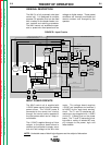
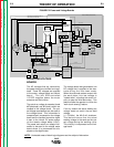
FIGURE E.4 Control Logic and Procedure Boards
NA-5
NOTE: Unshaded areas of block logic diagrams are the subject of discussion.
F1
A
R
M
A
T
U
R
E
F
I
E
L
D
V
O
L
T
A
G
E
V
O
L
T
A
G
E
T1 T2
OPTIONAL
START
BOARD
OPTIONAL
CRATER
BOARD
OPTIONAL
WELD
TIMER
BURNBACK
TIMER
VOLTAGE
BOARD
METER
BOARD
SPEED
VOLT
METER
BOARD
DIGITAL
METER
DIGITAL
METER
MOTOR
LOGIC
BOARD
CONTROL
BOARD
P
O
W
E
R
B
O
A
R
D
P
R
O
C
E
D
U
R
E
B
O
A
R
D
TACH
INCH
DOWN
SWITCH
STOP
SWITCH
START
SWITCH
WELD
CURRENT
REED SWITCH
CR
1
CR
2
CR
3
FLUX
RECEPTACLE
TRAVEL
RECEPTACLE
CONTACTOR CLOSURE (#2 AND #4)
REMOTE VOLTAGE CONTROL (A, B, C)
WORK SENSING (#21)
TACH FEEDBACK (MOTOR RPM)
DC SUPPLY VOLTAGE
10VDC REFERENCEVOLTAGE
DC VOLTAGE
S
I
G
N
A
L
INPUT
POWER
SWITCH
CIRCUIT
BREAKER
R1(2 OHMS)
MOTOR
G
A
T
E
S
I
G
N
A
L
S
CONTROL
CABLE
RECEPTACLE
TACH FEEDBACK (MOTOR RPM)
115VAC
36VAC (18+18VAC)
22VAC
1
V
A
C
0
D
C
S
U
P
P
L
Y
V
O
L
T
A
G
E
SIGNAL
A
R
C
V
O
L
T
A
G
E
S
H
U
T
D
O
W
N
A
N
D
INCH
UP
SWITCH
STRIKE/WELD PROCEDURE
ENABLE
FIELD
ARMATURE
F
E
E
D
E
N
A
B
L
E
DIRECTION
ARC VOLTS (SET & ACTUAL)
WIRE FEED SPEED (SET & ACTUAL)
E
L
E
C
T
R
ODE SENSING
(#67)
115
VAC
WELD
VOLTS SPEED
VOLTS SPEED
STRIKE
115VAC
#31
#32
1/2 AMP
F501
SET SPEED
SET VOLTAGE
START
TIMER
CRATER
TIMER
F2
Return to Section TOC Return to Section TOC Return to Section TOC Return to Section TOC
Return to Master TOC Return to Master TOC Return to Master TOC Return to Master TOC