


F-51
TROUBLESHOOTING & REPAIR
F-51
PROCEDURE
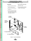
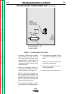
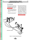
1. Make sure the electrode wire is fed
through the wire contact assembly
tip but NOT touching the "work"
piece.
2. Disconnect input power to the NA-5.
3. Make sure the drive motor cable and
power source control cables are
properly connected to the NA-5 con-
trol box.
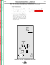
4. Using the 5/16" nutdriver open the
control box PC board access door.
5. Locate the TS1 terminal strip. See
wiring diagram.
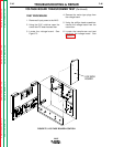
6. Using the ohmmeter check the resis-
tances per the following table F.2
7. Reconnect the welding cable leads
to the contact assembly.
8. If any of the resistances are not cor-
rect per Table F.2 check the associ-
ated leads, cables and circuits for
"opens" or "shorts". See wiring dia-
gram.
9. Close and secure the control box
access door.
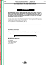
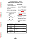
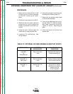
EXTERNAL RESISTANCE TEST (LEADS #21 AND #67) (Continued)
NA-5
TEST POINTS EXPECTED COMMENTS AND
RESISTANCES CONDITIONS
Lead #667 Zero or less than Electrode wire must be in
to 1 ohm contact assembly tip
Electrode wire
Lead #621 to Zero or less than Polarity switches must be
work piece 1 ohm in the correct positions
Lead #667 to Greater than 15K Using the 3/4" wrench
#621 ohms disconnect the welding
cable(s) from the
contact assembly
TABLE F.2 EXTERNAL VOLTAGE SENSING LEADS TEST POINTS
Return to Section TOC Return to Section TOC Return to Section TOC Return to Section TOC
Return to Master TOC Return to Master TOC Return to Master TOC Return to Master TOC