


OPERATING INSTRUCTIONS
B-3B-3
NA-5
CONTROLS AND
THEIR FUNCTIONS
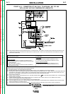
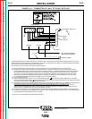
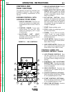
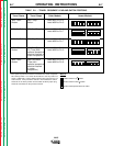
The operator controls for the NA-5 are
illustrated in Figure B.1. Refer to the figure
and the following explanations of the
controls.
EXPOSED CONTROLS (WITH
LOCKABLE COVER DOWN)
1. CIRCUIT BREAKER. Protects the
circuit from severe wire feed motor
overloads and short circuits. Press to
reset.
2. CONTROL POWER. Turns input
control power “On” and “Off.” Also
used as an emergency “Off” in case
of malfunction.
3. ELECTRODE “HOT” LIGHT.
Comes on when the “Start button” is
pressed and the electrode circuit
becomes electrically hot.
4. INCH UP AND INCH DOWN. Press to
inch electrode up or down.
5. MODE SELECTOR SWITCH AND
LIGHTS. Used to preset the voltage
and wire feed speed for the various
modes of operation (Strike, Start,
Weld, and Crater).
6. SET-ACTUAL BUTTON. When
pressed, will display the actual wire
speed and voltage in the wire speed
and volts meters. When the button is
not pressed, the set wire speed and
voltage is displayed.
7. START. Begins welding cycle.
8. STOP. Initiates the stopping cycle at
the end of the weld.
9. TRAVEL. Turn to “Off” for no travel,
“Hand Travel” for travel without
welding, and “Automatic Welding” for
welding operations.
10. VOLTS METER. Displays the set or
actual voltage for each mode (Strike,
Start, Weld, Crater).
11. WIRE SPEED METER. Displays the
set or actual wire speed for each
mode (Strike, Start, Weld, Crater).
CONTROLS UNDER THE
LOCKABLE SECURITY COVER
12. ARC STRIKING CONTROLS. Sets
the wire speed until the welding
current begins to flow and controls
the power source voltage during arc
striking.
13. BURNBACK AND ELECTRODE
BACKUP TIME. Controls the length
of burnback delay time after the stop
circuit is energized.
14. WELD CONTROLS. Controls the
voltage and wire speed during the
welding mode.
15. CRATER CONTROLS (OPTIONAL).
Sets the ending current and voltage
for an adjustable period of time.
16. START CONTROLS (OPTIONAL).
Sets the starting current and voltage
for an adjustable period of time.
17. WELD TIME (OPTIONAL). Controls
the time of the weld mode.
FIGURE B.1 – NA-5 CONTROLS.
9
2
3
12
11
17
16
10
15
13
7
6
8
4
14
5
1
Return to Section TOC Return to Section TOC Return to Section TOC Return to Section TOC
Return to Master TOC Return to Master TOC Return to Master TOC Return to Master TOC