


E-2
THEORY OF OPERATION
E-2
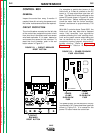
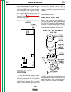
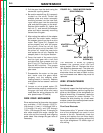
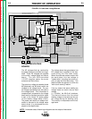
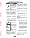
INPUT POWER CIRCUITS
The NA-5 control unit is supplied with
115VAC power usually from the welding
power source. The 115VAC power is
connected to the control box circuitry
through the control cable receptacle,
the input power switch and a 5 amp cir-
cuit breaker.
The 115VAC is applied through a 2 ohm
resistor to the power board where is
rectified and controlled to supply arma-
ture and field voltage to the wire drive
motor. The voltage board receives
115VAC and transforms and rectifies it
to 24VDC for the "work touch sensing"
circuit. The T1 and T2 transformer pri-
maries are also supplied with 115VAC
via the F1 (1/2amp) fuse on the power
board. The T1 and T2 secondary wind-
ings offer a variety of isolated AC sup-
ply voltages to the power, logic and
meter boards.
FIGURE E.1 Input Circuits
NA-5
F1
A
R
M
A
T
U
R
E
F
I
E
L
D
V
O
L
T
A
G
E
V
O
L
T
A
G
E
T1 T2
OPTIONAL
START
BOARD
OPTIONAL
CRATER
BOARD
OPTIONAL
WELD
TIMER
BURNBACK
TIMER
VOLTAGE
BOARD
METER
BOARD
SPEED
VOLT
METER
BOARD
DIGITAL
METER
DIGITAL
METER
MOTOR
LOGIC
BOARD
CONTROL
BOARD
P
O
W
E
R
B
O
A
R
D
P
R
O
C
E
D
U
R
E
B
O
A
R
D
TACH
INCH
DOWN
SWITCH
STOP
SWITCH
START
SWITCH
WELD
CURRENT
REED SWITCH
CR
1
CR
2
CR
3
FLUX
RECEPTACLE
TRAVEL
RECEPTACLE
CONTACTOR CLOSURE (#2 AND #4)
REMOTE VOLTAGE CONTROL (A, B, C)
WORK SENSING (#21)
TACH FEEDBACK (MOTOR RPM)
DC SUPPLY VOLTAGE
10VDC REFERENCEVOLTAGE
DC VOLTAGE
S
I
G
N
A
L
INPUT
POWER
SWITCH
CIRCUIT
BREAKER
R1(2 OHMS)
MOTOR
G
A
T
E
S
I
G
N
A
L
S
CONTROL
CABLE
RECEPTACLE
TACH FEEDBACK (MOTOR RPM)
115VAC
36VAC (18+18VAC)
22VAC
1
V
A
C
0
D
C
S
U
P
P
L
Y
V
O
L
T
A
G
E
SIGNAL
A
R
C
V
O
L
T
A
G
E
S
H
U
T
D
O
W
N
A
N
D
INCH
UP
SWITCH
STRIKE/WELD PROCEDURE
ENABLE
FIELD
ARMATURE
F
E
E
D
E
N
A
B
L
E
DIRECTION
ARC VOLTS (SET & ACTUAL)
WIRE FEED SPEED (SET & ACTUAL)
E
L
E
C
T
R
ODE SENSING
(#67)
115
VAC
WELD
VOLTS SPEED
VOLTS SPEED
STRIKE
115VAC
#31
#32
1/2 AMP
F501
SET SPEED
SET VOLTAGE
START
TIMER
CRATER
TIMER
F2
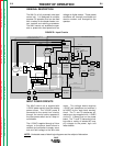
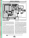
NOTE: Unshaded areas of block logic diagrams are the subject of discussion.
GENERAL DESCRIPTION
The NA-5 is a fully automatic wire feed
control unit. It is designed for multiple
process CV operation and can be used
with a variety of wire feeder heads, con-
tact nozzles and welding processes.
The NA-5 control unit enables the oper-
ator to preset wire feed speed and arc
voltage on digital meters. These preset
conditions are internally monitored and
remain constant until changed by the
operator.
Return to Section TOC Return to Section TOC Return to Section TOC Return to Section TOC
Return to Master TOC Return to Master TOC Return to Master TOC Return to Master TOC