


F-24
TROUBLESHOOTING & REPAIR
F-24
NA-5
Observe all Safety Guidelines detailed throughout this manual
If for any reason you do not understand the test procedures or are unable to perform the tests/repairs safely, contact the Lincoln Electric
Service Department for technical troubleshooting assistance before you proceed. Call 216-383-2531 or 1-800-833-9353.
CAUTION
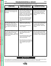
FUNCTION PROBLEMS
PROBLEMS
(SYMPTOMS)
POSSIBLE AREAS OF
MISADJUSTMENTS(S)
RECOMMENDED
COURSE OF ACTION
After pressing the stop button, the
electrode “Hot” light goes OFF, but
the electrode wire remains electrical-
ly hot. (The welding voltage is
always present). The wire stops
feeding.
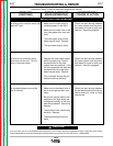
After pressing the stop button, the
weld light remains on and the wire
continues to feed.
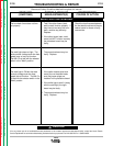
The set and actual speed meter
readings match within a few IPM, but
both are in error.
1. Carefully disconnect the #2 lead
from the power source terminal
strip. The welding voltage should
be disabled. If the welding volt-
age is still present the power
source is faulty.
2. Check or replace the control
cable between the power source
and the NA-5 unit.
1. If a crater option module is used,
check to make sure the logic
board jumper (#694) is on pin
P10.
2. While pressing the stop button
observe light 7C located on the
logic board. It should be lit. If
light 7C is ON and the wire feed-
ing and welding does not stop,
the logic board may be faulty.
1. Made sure the calibration jumper
on the speedmeter board is con-
nected properly. See
Operation
Section.
1. The 3CR relay may be faulty.
The contacts (terminals 2 and 4)
may be stuck closed.
2. Check the associated leads for
misconnections. See wiring dia-
gram.
1. If, while pressing the stop button,
light 7C does NOT go on, check
the stop button and associated
leads.
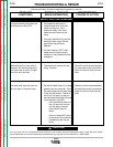
1. Remove the drive motor end cap
and the tach cover plate from the
end of the wire drive motor.
Check to make sure the slotted
disc is secure and aligned and
rotates freely through the center
of the module pick-up.
2. Perform the
Wire Speed
Accuracy Test
3. Perform the
Meter Circuit
Accuracy Test.
4. The control board may be faulty.
Replace.
Return to Section TOC Return to Section TOC Return to Section TOC Return to Section TOC
Return to Master TOC Return to Master TOC Return to Master TOC Return to Master TOC