


F-58
TROUBLESHOOTING & REPAIR
F-58
TEST PROCEDURE
Perform the following checks with the
NA-5 connected to a Lincoln CV weld-
ing power source according to the prop-
er connection diagram. See the
Installation Section
of this manual.
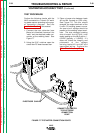
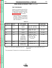
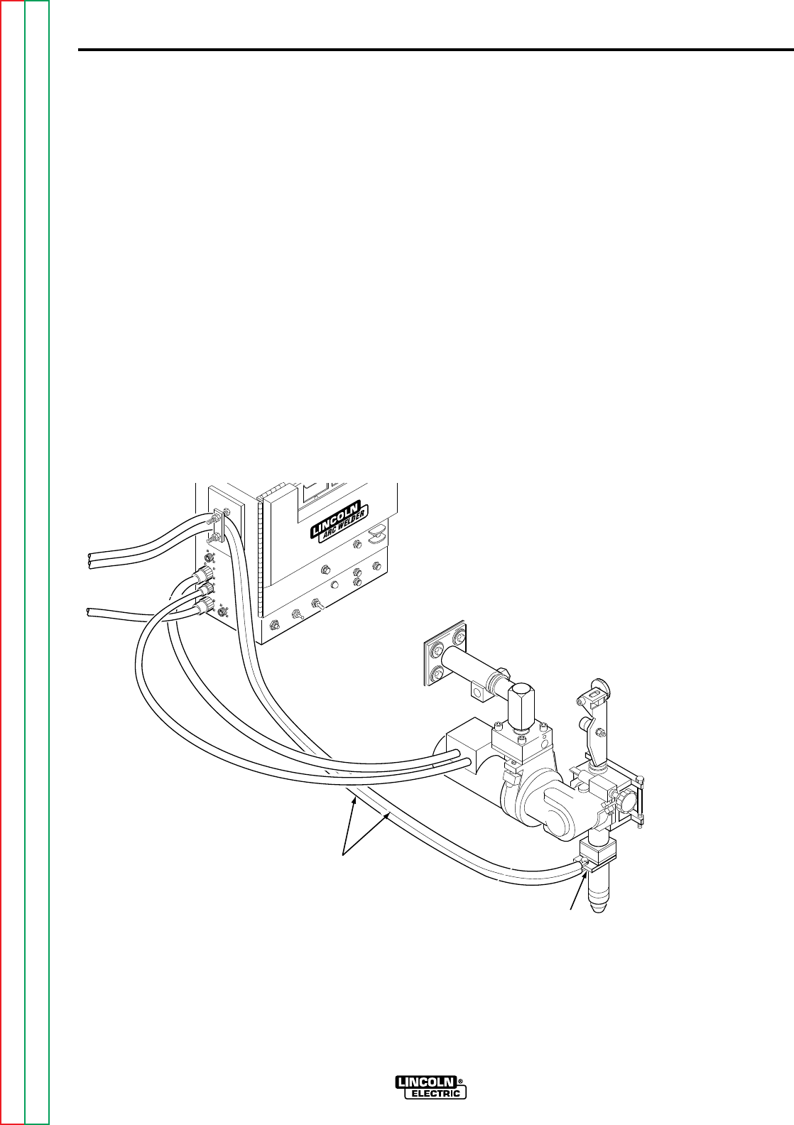
1. Connect the test voltmeter (see
Materials Needed) between the
"work" and the electrode cable con-
nection at the welding head. See
Figure F.7
2. Using the 5/16" nutdriver open the
control box PC board access door.
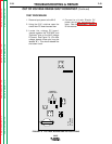
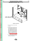
3. Place a jumper wire between leads
#2 and #4 located on CR3 relay.
See Figure F.8 This this should
energize the output terminals of the
Lincoln CV welding power source.
An open circuit voltage should be
present at the welding output termi-
nals. The test voltmeter reading
should match the ACTUAL volts
meter reading on the NA-5 within +/-
0.5VDC (typically +/- 0.2VDC). If it
does not, check the integrity and
placement of the voltage
sensing leads #21 and #67 and
associated wiring. Perform the
Meter Circuit Accuracy Test
.
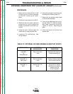
VOLTMETER ACCURACY TEST (Continued)
NA-5
FIGURE F.7 TEST METER CONNECTION POINTS
CONNECT VOLTMETER
TO ELECTRODE
CONNECTION
POINT
ELECTRODE CABLES
Return to Section TOC Return to Section TOC Return to Section TOC Return to Section TOC
Return to Master TOC Return to Master TOC Return to Master TOC Return to Master TOC