


F-68
TROUBLESHOOTING & REPAIR
F-68
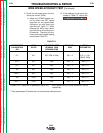
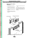
9. Locate the speedmeter PC board.
See Figure F.10
10. Apply input power to the NA-5.
11. Test for AC supply to the speed-
meter PC board.
• Check for 8 to 11VAC from lead
#601 ot #602. See Figure F.10
Note: The coating will have to be
removed from the test points to ensure
accurate voltmeter readings. If the cor-
rect AC voltage is not present check for
loose or faulty connects with the associ-
ated leads. See wiring diagram.
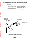
12. Test for DC volts on the speed-
meter PC board.
• Check for 4.75 to 5.25VDC from
TP5 to lead #510P. See Figure
F.10
Note: The coating will have to be
removed from the test points to ensure
accurate meter readings.
• If the display is NOT lit and the
correct DC voltage is present at
TP5 to lead #510P, the digital
meter may be faulty. Replace the
meter.
• If the AC voltage IS present at
leads #601 to #602 and the DC
voltage is missing, the speedme-
ter PC board may be faulty.
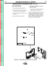
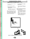
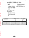
METER CIRCUIT ACCURACY TEST (Continued)
NA-5
FIGURE F.10 SPEEDMETER PC BOARD AND TEST POINTS
NA5 SPEED METER L6233
TP4
TP5
510
510P
601
602
Return to Section TOC Return to Section TOC Return to Section TOC Return to Section TOC
Return to Master TOC Return to Master TOC Return to Master TOC Return to Master TOC