


OPERATING INSTRUCTIONS
B-4B-4
NA-5
SETUP INSTRUCTIONS
Use the following steps to set up the NA-5
welding system prior to welding:
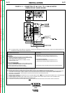
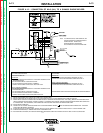
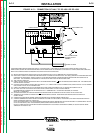
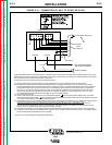
1. If using a multi-process power source
(SAM, DC-400, DC-600, DC-1000,
OR DC-1500 type), make con-
nections and settings per the power
source connection diagram (Figures
A.8 to A.14) for the process being
used.
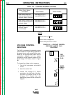
AUTO TAB
When using the NA-5 with the DC-
400 or CV-400 power source, the
auto tab jumper on the NA-5 voltage
PC board must be connected in order
for the inch down circuit to function.
When the auto tab jumper is
connected, the cold starting feature
of the NA-5 is disabled and only the
hot starting technique can be used. If
the cold start technique is to be used,
the optional Diode must be installed
on the DC-400 or CV-400.
2. Set the power source and NA-5
circuit polarity per information on
Electrode Polarity
in Section A,
Installation.
3. Depending on the procedures and
applications, decide:
a. The means of arc striking and
whether to start the travel with
the “Start” button or the arc.
b. Whether the initial bead size or
penetration requires use of the
optional “Start Controls.”
See the
Starting and Stopping
Sequences
section.
4. Depending upon the procedures and
applications:
a. Select the arc and travel stopping
sequence. See the
Starting and
Stopping Sequences
section.
b. Decide if the control of the ending
bead size or crater fill requires
the use of optional “Crater
Controls”. See the
Starting and
Stopping Sequences
section.
5. Set the head position relative to the
work as required for the fixture,
application, and procedures. See
IM305 Sec. T3.2.3.
6. Rotate the wire straightener, if used,
until the top of the straightener faces
the wire reel. This is required for
smooth feeding of the electrode into
the straightener.
7. Refer to the instructions for the wire
contact assembly being used. See
IM305 Sec. T2.2.6, T2.2.7, T2.5.3, or
T2.5.4.
8. The mount for standard 50 and 60 lb
(22.7 and 27.2 kg) electrode coils
includes a two-position brake
assembly. Generally the brake should
be at the inner position (nearest to
the wire reel shaft) for wire feed
speeds below 400 in./min (10 m/min).
It should be at the outer position for
faster wire speeds. To adjust the
brake position, remove the wire reel.
Pull the cotter pin that holds the
brake shoe to the arm, move the
shoe, and replace the cotter pin. Do
not bend the cotter pin — it is held in
place by a friction fit.
9. Load the wire reel per IM305 Sec.
T3.2.2 or install the Speed-Feed
drum or reel per Sec. T2.5.7-A or -B.
10. Straighten the first 6 in. (152.4 mm)
of electrode and push it through the
wire straightener to the drive rolls. To
use the cored wire straightener,
remove the knurled nut at the top and
feed the wire through the nut, down
through the straightener, and into the
drive rolls. Screw the nut back onto
the straightener. Feed the wire
through the nozzle tip and adjust
the straightener for optimum
straightness. With wire contact
assemblies, except the K231, adjust
until the electrode is straight as it
comes out of the nozzle. Do not
completely straighten the wire when
using the K231 contact nozzle
because the nozzle relies on the
small curvature of the electode for
proper electrical contact within the
contact tip.
Return to Section TOC Return to Section TOC Return to Section TOC Return to Section TOC
Return to Master TOC Return to Master TOC Return to Master TOC Return to Master TOC