


F-39
TROUBLESHOOTING & REPAIR
F-39
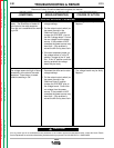
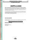
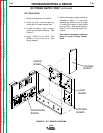
TEST PROCEDURE
1. Remove input power to the NA-5.
2. Using the 5/16" nutdriver open the
control box PC board access door.
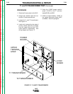
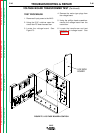
3. Locate the power, logic, voltage,
control and procedure boards. See
Figure F.1
4. Apply 115VAC to the NA-5 wire
feeder at the correct pins. See
wiring diagram.
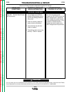
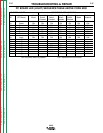
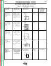
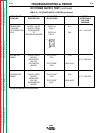
5. Perform the power supply checks as
described in Table F.1 If any of the
readings are incorrect (out of range)
or missing the power or logic board
may be faulty. See wiring diagram.
Note: Do not unplug the molex con-
nectors.
Also check associated leads and
plugs for loose or faulty connec-
tions.
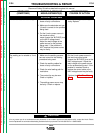
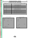
DC POWER SUPPLY TEST (continued)
NA-5
FIGURE F.1 P.C. BOARD LOCATIONS
PROCEDURE
BOARD
POWER
BOARD
LOGIC
BOARD
CONTROL
BOARD
VOLTAGE
BOARD
Return to Section TOC Return to Section TOC Return to Section TOC Return to Section TOC
Return to Master TOC Return to Master TOC Return to Master TOC Return to Master TOC