


PRECISION TIG 185
TROUBLESHOOTING & REPAIR
F-47 F-47
Return to Section TOC Return to Section TOC Return to Section TOC Return to Section TOC
Return to Master TOC Return to Master TOC Return to Master TOC Return to Master TOC
POLARITY SWITCH
REMOVAL AND REPLACEMENT PROCEDURE (Continued)
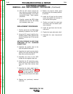
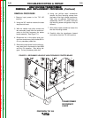
REPLACEMENT PROCEDURE
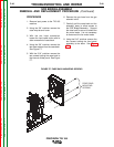
1. Carefully position the new polarity
switch in position on the front panel.
Make certain the micro-switch is
assembled to the polarity switch cor-
rectly.
2. Solder leads #311 and #312 to the
micro -switch.
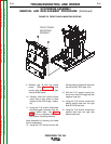
3. Assemble and tighten the two nuts
and washers that hold the polarity
switch to the front panel.
4. Assemble the X1 secondary lead to
the polarity switch. Make certain
washers are in place and the nut is
tight.
5. Assemble the choke lead to the
polarity switch. Make certain wash-
ers are in place and the nut is tight.
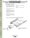
6. Assemble the flat copper leads to the
polarity switch. Make certain they
are connected to the proper termi-
nals and the nuts are tightened.
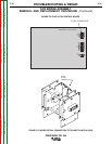
7. Assemble the flex lead from diode
D1 to the rear gang of the polarity
switch. Make certain washers are in
place and the nut is tight.
8. Assemble the flex lead from the AC
bridge plate to the polarity switch.
Make certain washers are in place
and the nut is tight.
9. Assemble the “positive” flex lead to
the polarity switch. Make certain
washers are in place and the nut is
tight.
10. Clear the leads and check for
“shorted” or “grounded” leads.
11. Position the name plate and fasten
to the front with the previously
removed snap rivets.
12. Assemble the polarity switch handle
in place with the Phillips head screw
and check for correct switch opera-
tion.
13. Using the Allen type wrench replace
the output control knob.
14. Replace the case wrap-around
cover.