


PRECISION TIG 185
TROUBLESHOOTING & REPAIR
F-55 F-55
Return to Section TOC Return to Section TOC Return to Section TOC Return to Section TOC
Return to Master TOC Return to Master TOC Return to Master TOC Return to Master TOC
MAIN TRANSFORMER AND OUTPUT CHOKE ASSEMBLY
REMOVAL AND REPLACEMENT PROCEDURE (Continued)
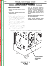
REPLACEMENT PROCEDURE
1. Position the new transformer/choke
assembly onto the base and mount-
ing bolts.
2. Assemble the four nuts and washers
to the mounting bolts on the base of
the machine.
3. Assemble the X1 secondary lead to
the polarity switch.
4. Assemble the choke lead to the
polarity switch.
5. Install the J3 plug into the control
board.
6. Assemble the H1, H2 or H3 lead onto
the input power switch. Insulate and
secure the unused lead (H2 or H3).
7. Assemble the shunt assembly to the
choke lead.
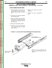
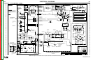
8. Solder leads R209 and U210 to the
main transformer leads. See wiring
diagram. Insulate connections.
9. Solder leads W201 and W204 to the
main transformer leads. See wiring
diagram. Insulate connections.
10. Solder the two 115VAC leads and
leads B231 and B232 to the main
transformer leads. See wiring dia-
gram. Insulate connections.
11. Replace any previously removed
cable ties. Clear leads and check
for “shorts” or “grounds”.
12. Perform the SCR Bridge
Assembly Replacement
Procedure.