


Return to Section TOC Return to Section TOC Return to Section TOC Return to Section TOC
Return to Master TOC Return to Master TOC Return to Master TOC Return to Master TOC
B-5
OPERATION
B-5
WIRE-MATIC 250
USING THE WIRE DRIVE ROLL
The drive roll provided with the WIRE-MATIC 250 has
two grooves, one for.030-.035" (0.8-0.9mm) solid steel
electrode, and the other for .045" (1.2mm) solid steel
electrode. The welder is shipped with the drive roll
installed in the .030-.035" (0.8-0.9mm) position as indi-
cated by the stenciling on the exposed side of the drive
roll. If .045" (1.2mm) electrode is to be used or one of
the optional drive rolls is required, then the drive roll
must be reversed or changed per the following instruc-
tions. This information also appears on the Procedure
Decal on the door inside the wire compartment.
PROCEDURE FOR CHANGING DRIVE
ROLL
Different wire sizes may require changing the drive roll.
The applicable wire sizes are stamped on the drive roll.
Dual groove rolls must be installed so the side with the
proper wire size stamp faces out.
1. Turn POWER SWITCH to OFF.
2. Release the pressure on the idle roll by swinging
the pressure arm off the idle roll arm.
3. Remove the wire from the drive system.
4. Remove the wing screw from the drive roll.
5. Turn the drive roll over or change to another roll as
required.
6. Replace the wing screw.
7. Check that the gun liner and contact tip are prop-
erly sized for wire being used.
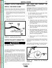
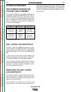
LOADING THE WIRE REEL
To mount a 22-30 lb. (10-14 kg) Readi-Reel package
using the optional Readi-Reel Adapter (K363P):
1. Pull the spindle up out of the WIRE-MATIC 250
spindle mounting clips (V-brackets).
2. Snap the spindle into the Readi-Reel adapter so
the spindle drive pin is engaged with the hole pro-
vided in the Adapter.
3. Rotate the spindle and adapter so the retaining
spring is at the 12 o'clock position.
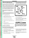
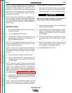
4. Position the Readi-Reel so that it will rotate in a
counterclockwise direction (as viewed from retain-
ing spring side of Adapter) when wire is dereeled
from the top of the coil as shown in Figure B.2.
FIGURE B.2 - Wire Reel Loading.
5. Set one of the Readi-Reel inside cage wires on the
slot in the retaining spring tab.
6. Lower the Readi-Reel to depress the retaining
spring and align the other inside cage wires with
the grooves in the molded adapter.
7. Slide the cage all the way onto the adapter until the
retaining spring "pops" up fully.
Check to be sure the retaining spring has fully
returned to the locking position and has securely
locked the Readi-reel cage in place. Retaining
spring must rest on the cage not the welding elec-
trode.
____________________________________
8. Check that the mating surfaces of the spindle hubs
and spindle mounting clips (V-brackets) are clear
of dirt and debris, and that the adapter is fully
engaged onto the spindle.
9. Lower the loaded spindle into the spindle mounting
clips (V-brackets) so wire dereels from top of coil
toward wire drive.
WARNING