


B-6
OPERATION
B-6
NOTE: The retaining spring side of the adapter should
be facing the center (inner) panel of the WIRE-MATIC
250.
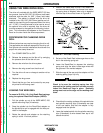
10. Remove Readi-Reel from Adapter by depressing
the retaining spring tab with thumb while pulling
the Readi-Reel cage from the molded adapter with
both hands. Do not remove adapter from spindle.
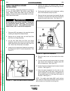
To mount 10 to 30 lb. spools (8" and 12" diameter):
1. Remove the optional Readi-Reel adapter from the
2 inch dia. spindle, if installed.
2. Check the mating surfaces of the spindle hubs and
spindle mounting clips (V-brackets) to be sure they
are clear of dirt and debris.
3. Place the spool on the spindle. Make certain the
brake driving pin enters one of the holes in the
back side of the spool.
4. Lower the loaded spindle into the spindle mount-
ing clips (V-brackets) so the wire dereels from the
top of the reel toward the wire drive.
NOTE: The WIRE-MATIC 250 Spindle was designed
to mount 12" (300mm) and 8" (200mm) diameter
spools meeting international spool size specifications.
If the spool being used is too narrow to keep the brake
driving pin* engaged with the spool pin hole, a 2"
(51mm) I.D. shim washer could be used between the
spool and the spindle retaining clip to take up the
space.
* Later spindle design uses a longer D-shaped pin to
assure engagement.
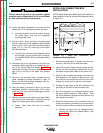
FEEDING ELECTRODE
When inching, the electrode and drive mechanism
are electrically hot to work and ground. The elec-
trode remains hot several seconds after the gun
trigger is released.
____________________________________
NOTE: Check that the proper drive rolls and gun parts
for the wire size and type are being used.
1. Turn the Readi-Reel or spool until the free end of
the electrode is accessible.
2. Tightly holding the electrode, cut off the bent end
and straighten the first six inches.
a. If the electrode is not properly straightened, it
may not feed properly into the outgoing guide
tube or welding gun causing a "birdnest.")
3. Cut off the first inch.
4. Push the wire through the ingoing guide tube.
5. Press the gun trigger and push the electrode into
the drive roll.
a. If the electrode fails to thread itself into the out-
going guide tube of the wire drive
• open the quick release idle roll arm
• thread the electrode manually
• re-close the arm.
6. Inch the electrode through the gun.
NOTE: Due to the low speed starting feature of the
WIRE-MATIC 250, the wire will feed at low speed for 2
seconds while inching, then come up to the set speed.
To change run-in mode, see the
Changing the Run In
Mode Section
.
PROPER WIRE FEEDING
Wire feeding problems can be avoided by observing
the following gun handling procedures:
• Do not kink or pull cable around sharp corners.
• Keep the electrode cable as straight as possible
when welding or loading electrode through cable.
• Do not allow dolly wheels or trucks to run over
cables.
• Keep cable clean by following maintenance
instructions.
• Use only clean, rust-free electrode. The Lincoln
electrodes have proper surface lubrication.
• Replace contact tip when the arc starts to become
unstable or the contact tip end is fused or
deformed.
• Keep drop-in spindle and spindle mounting clip
contacting surfaces clear of dirt and debris.
WIRE-MATIC 250
Return to Section TOC Return to Section TOC Return to Section TOC Return to Section TOC
Return to Master TOC Return to Master TOC Return to Master TOC Return to Master TOC
WARNING