


Return to Section TOC Return to Section TOC Return to Section TOC Return to Section TOC
Return to Master TOC Return to Master TOC Return to Master TOC Return to Master TOC
F-23
TROUBLESHOOTING & REPAIR
F-23
WIRE-MATIC 250
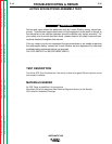
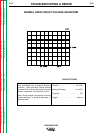
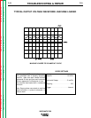
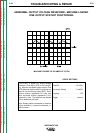
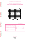
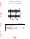
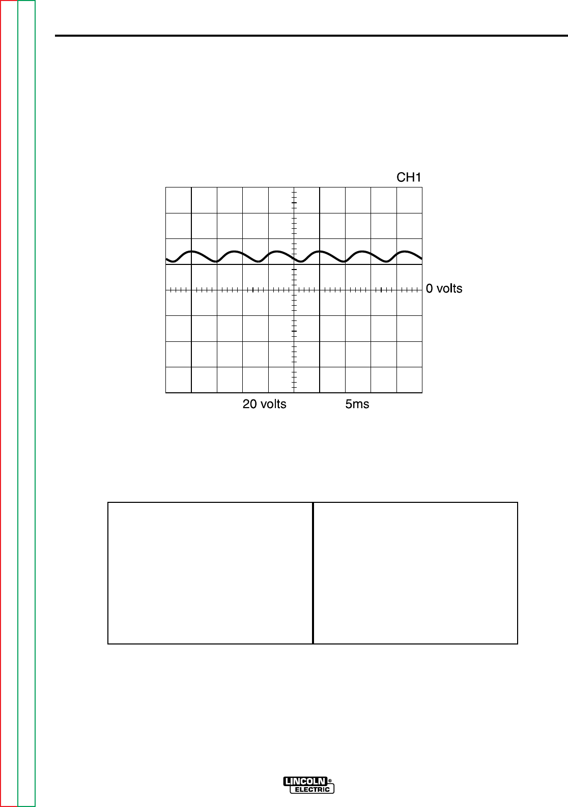
This is a typical DC output voltage wave-
form generated from a properly operating
machine. Note that each vertical division
represents 20 volts and that each horizontal
division represents 5 milliseconds in time.
The machine was loaded with a resistance
grid bank.
Note: Scope probes connected at machine
output terminals: (+) probe to electrode, (-)
probe to work.
Volts/Div . . . . . . . . . . . . . . . . .20 V/Div.
Horizontal Sweep . . . . . . . . . .5 ms/Div.
Coupling . . . . . . . . . . . . . . . . . . . . .DC.
Trigger . . . . . . . . . . . . . . . . . . .Internal.
SCOPE SETTINGS
MACHINE LOADED TO 250 AMPS AT 26 VDC
TYPICAL OUTPUT VOLTAGE WAVEFORM - MACHINE LOADED