


B-7
OPERATION
B-7
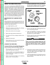
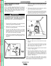
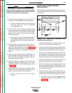
SETTING IDLE ROLL PRESSURE
The idle roll pressure wing screw is set at the factory
backed out 2-1/2 turns from full pressure. This is an
approximate setting. The optimum idle roll pressure
varies with type of wire, wire diameter, surface condi-
tions, lubrication, and hardness. As a general rule,
hard wires may require greater pressure, and soft, or
aluminum wire, may require less pressure than the fac-
tory setting. The optimum idle roll setting can be deter-
mined as follows:
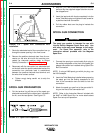
1. Push the end of gun against a solid object that is
electrically isolated from the welder output.
2. Press the gun trigger for several seconds.
a. If the wire "birdnests", jams, or breaks at the
drive roll, the idle roll pressure is too great.
Back the wing screw out 1/2 turn, run new wire
through gun, and repeat steps 1 and 2.
b. If the drive roll slips, loosen the wing screw on
the conductor block and pull the gun cable for-
ward about 6" (15 cm). There should be a
slight waviness in the exposed wire. If there is
no waviness, the pressure is too low. Tighten
the wing screw 1/4 turn, reinstall the gun
cable, and repeat steps 1 and 2.
OPERATING STEPS
Before operating the machine, be sure you have all
the materials needed to perform the work. Be sure
you are familiar with and have taken all possible
safety precautions before starting the work. It is
important that you follow these operating steps
each time you use the machine.
___________________________________
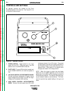
STARTING THE WELDER
1. Turn the POWER switch to ON. This illuminates
the red LED pilot light.
2. Select the correct voltage and wire speed for the
welding process required.
3. Operate the gun trigger for welder output and to
energize the wire feeder motor.
NOTE: When the POWER SWITCH is ON, the fan
motor is thermostatically controlled to provide cooling
for the transformer and other components only when
the machine needs cooling. When the machine does
not require fan cooling the fan does not run, such as
when first turned on, when welding at low current, or at
low duty cycle procedures.
CHANGING RUN-IN MODE (Later models
only)
The WIRE-MATIC 250 is factory set for slow run-in
mode. This means the machine will initially feed wire
at 50 IPM until output current is sensed or for 2.0 sec-
onds, whichever occurs first. After which it will accel-
erate to the preset wire feed speed.
In the Fast run-in mode, the machine will accelerate
directly to the preset wire feed speed.
ENTER FAST RUN-IN MODE
1. Turn POWER SWITCH to OFF on front panel of
WIRE-MATIC 250.
2. Turn the WIRE SPEED CONTROL POTEN-
TIOMETER KNOB fully clockwise to maximum.
3. Close the gun trigger switch and turn the POWER
SWITCH to ON.
a. The gas solenoid will actuate four times to sig-
nal that the unit has entered the fast run-in
mode. The gun trigger need only be closed
until the first gas solenoid actuation is heard.
NOTE: Arc starting characteristics may be effected
when using the fast run-in mode since normal starting
processes are being overridden.
ENTER SLOW RUN-IN MODE
1. Turn POWER SWITCH to OFF on front panel of
WIRE-MATIC 250.
2. Turn the WIRE SPEED CONTROL POTEN-
TIOMETER KNOB fully counterclockwise to mini-
mum.
3. Close the gun trigger and turn the POWER
SWITCH to ON.
a. The gas solenoid will actuate two times to sig-
nal that the unit has entered the slow run-in
mode. The gun trigger need only be closed
until the first gas solenoid actuation is heard.
WIRE-MATIC 250
Return to Section TOC Return to Section TOC Return to Section TOC Return to Section TOC
Return to Master TOC Return to Master TOC Return to Master TOC Return to Master TOC
WARNING