


C-3
ACCESSORIES
C-3
Collect metal filings with a rag to protect against
possible metal contamination of the control board
or other internal electrical components.
____________________________________
12. Fasten the panel receptacle to the case with the
three #6-32 x 3/8" self tapping screws provided.
a. Insert the screws from wire drive side, through
the sheet metal, and into the receptacle
mounting plate holes.
13. Plug the 10-pin, 8-pin, and 6-pin connector plugs
from the other end of the receptacle lead harness
into the 10-pin, 8-pin, and 6-pin connectors (Molex
plugs J12, J11, and J13) at the top of the Spool
Gun Module Board.
a. Plug the 8-pin connector at the opposite end of
this harness into the unused 8-pin connector
on the WIRE-MATIC 250 control board (Molex
plug J4).
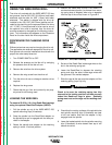
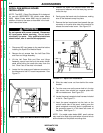
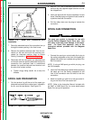
14. Disconnect the 4-pin gas solenoid plug from the
receptacle (Molex plug J8) on the upper right cor-
ner of the Control Board as shown Figure C.1.
Reconnect this plug to the 4-pin receptacle (Molex
plug J14) on the top of the Spool Gun Module
Board.
15. Plug the 4 pin connector plug, included with the
panel receptacle harness connected in step 13
above, into the Control Board receptacle (J8), dis-
connected in step 14 above.
16. Using the cable tie included in the kit, tie the two
harnesses together approximately 3.50 inches
(88.9 mm) from the end of the lead plugs as shown
in Figure C.1.
17. Replace the Case into the slots in the base. Make
sure the lip of the case side is lifted over the top
edge of the center panel during installation.
a. Fasten Case Side with the six screws
removed.
SPOOL GUN CONNECTION BOX
INSTALLATION
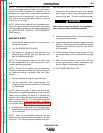
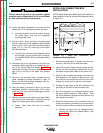
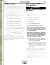
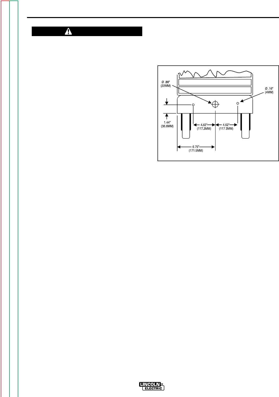
NOTE: Model codes below 9900 require the addition of
three holes to the front of the machine's base as shown
in Figure C.3.
FIGURE C.3 - Spool Gun Connection Box
Installation Mounting Holes.
1. Remove the plug button, if present, from the cen-
ter hole in the front of the machine's base.
2. Insert the two #10 thread forming screws (provid-
ed with the kit) and partially thread them into the
two small holes on both sides of the center hole.
3. Route a user provided gas supply hose from the
flow regulator of the spool gun gas cylinder, over
the rear axle of the machine, and out to the front
through the center hole in the front of the base.
4. Connect the gas hose to the 5/8-18 female inert
gas fitting on the back of the connection box.
5. Slip the connection box mounting keyholes over
the screw heads installed in Step 2 above. Pivot
the box clockwise to engage and level the box and
then tighten the screws.
6. Route the control cable of the connection box up
through the opening provided for the work lead in
the front louver and then up behind the wire drive.
a. Connect the plug to the kit receptacle when
installing the Spool Gun Module Board. See
Figure C.4.
WIRE-MATIC 250
Return to Section TOC Return to Section TOC Return to Section TOC Return to Section TOC
Return to Master TOC Return to Master TOC Return to Master TOC Return to Master TOC
CAUTION