


Return to Section TOC Return to Section TOC Return to Section TOC Return to Section TOC
Return to Master TOC Return to Master TOC Return to Master TOC Return to Master TOC
F-34
TROUBLESHOOTING & REPAIR
F-34
WIRE-MATIC 250
PROCEDURE
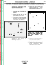
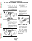
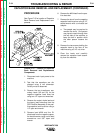
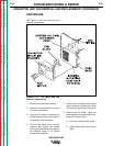
See Figure F.15 for location of Capacitor
Bank Removal and Replacement com-
ponents.
FIGURE F.15 - Location of Capacitor
Bank Removal and Replacement
Components.
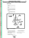
1. Disconnect main input power to the
machine.
2. Test that the capacitors are dis-
charged using a volt ohmmeter.
Polarity must be observed.
3. Remove the two transformer sec-
ondary leads (X2 and X3) for the
negative capacitor bank buss bar
using two 1/2" open end wrenches.
4. Remove the output choke lead and
the heavy lead extending from the
SCR Rectifier Assembly to the posi-
tive capacitor bank buss bar using a
1/2" open end wrench.
5. Remove lead #206 and the D1
diode lead from the negative capac-
itor bank buss bar using a slot head
screwdriver and 3/8" open end
wrench.
6. Remove the #204 lead from the pos-
itive buss bar.
7. Remove the shunt from the negative
capacitor bank buss bar using a 1/2"
socket wrench with a universal tool
adapter.
a. Two people may be required to
remove the shunt. One person
may have to reach through from
the left side of the machine to
keep the bolt in position while
the other person loosens the
nut.
8. Remove the two screws holding the
capacitor bank to the floor of the
machine using a 5/16" nut driver.
9. Clear the leads and carefully
remove the capacitor bank assem-
bly from the machine.
CAPACITOR BANK REMOVAL AND REPLACEMENT (CONTINUED)