


Return to Section TOC Return to Section TOC Return to Section TOC Return to Section TOC
Return to Master TOC Return to Master TOC Return to Master TOC Return to Master TOC
F-28
TROUBLESHOOTING & REPAIR
F-28
WIRE-MATIC 250
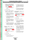
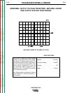
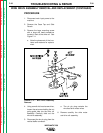
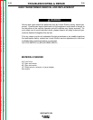
4. Remove the eight Phillips Head
mounting screws using a Phillips
Head screwdriver. See Figure F.10.
FIGURE F.10 - Control Board
Mounting Screw Locations may
vary with different Code
Machines.
5. Lift the Control Board straight up
and out from the machine.
6. Replace all mounting screws and
wiring connections when
installing the Control Board.
CONTROL PC BOARD REMOVAL AND REPLACEMENT (CONTINUED)
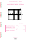
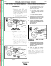
REMOVAL AND REPLACE-
MENT PROCEDURE
1. Disconnect main input power the
machine.
2. Remove the Case Top and Side
Panels using 5/16" nut driver.
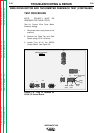
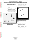
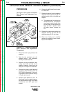
3. Disconnect all wiring harness plugs
and Molex Plugs connected to the
Control Board. See Figure F.9.
FIGURE F.9 - Wiring Harness and
Molex Plug Locations.
G2332
WM-250 CONTROL
J2
J7
J4
J10
J6
J9
J3
J5
J1