


Return to Section TOC Return to Section TOC Return to Section TOC Return to Section TOC
Return to Master TOC Return to Master TOC Return to Master TOC Return to Master TOC
F-26
TROUBLESHOOTING & REPAIR
F-26
WIRE-MATIC 250
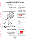
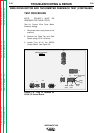
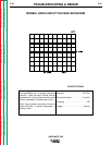
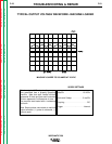
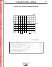
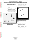
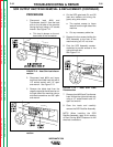
This is a typical SCR gate pulse voltage
waveform. The machine was in an open cir-
cuit condition (no load) and operating prop-
erly. Note that each vertical division repre-
sents 2 volts and each horizontal division
represents 5 milliseconds in time.
Note: Scope probes connected at Plug J3
on the control board. The (+) probe to lead
G2, and the (-) probe to lead 204.
Volts/Div . . . . . . . . . . . . . . . . . .2 V/Div.
Horizontal Sweep . . . . . . . . . .5 ms/Div.
Coupling . . . . . . . . . . . . . . . . . . . . .DC.
Trigger . . . . . . . . . . . . . . . . . . .Internal.
SCOPE SETTINGS
TYPICAL SCR GATE VOLTAGE WAVEFORM