


14
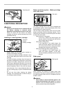
the blade to its fully elevated position.
WARNING:
• After setting the blade for a bevel cut, before
operating the tool ensure that the carriage and
blade will have free travel throughout the entire
range of the intended cut. Interruption of the
carriage or blade travel during the cutting operation
may result in kickback and serious personal injury.
• While making a bevel cut keep hands out of the
path of the blade. The angle of the blade may
confuse the operator as to the actual blade path
while cutting and contact with the blade will result in
serious personal injury.
• The blade should not be raised until it has
come to a complete stop. During a bevel cut the
piece cut off may come to rest against the blade. If
the blade is raised while it is rotating the cut-off
piece maybe ejected by the blade causing the
material to fragment which may result in serious
personal injury.
NOTICE:
• When pressing down the handle, apply pressure in
parallel with the blade. If a force is applied
perpendicularly to the turn base or if the pressure
direction is changed during a cut, the precision of
the cut will be impaired.
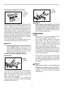
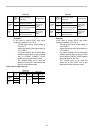
5. Compound cutting
Compound cutting is the process in which a bevel
angle is made at the same time in which a miter
angle is being cut on a workpiece. Compound
cutting can be performed at the angle shown in the
table.
Miter angle
Left and Right 45
Right 50
Right 55
Right 57
Bevel angle
Left 0 - 45
Left 0 - 40
Left 0 - 30
Left 0 - 25
006393
When performing compound cutting, refer to "Press
cutting", "Slide cutting", "Miter cutting" and "Bevel
cut" explanations.
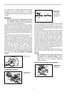
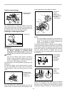
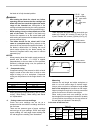
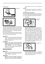
6. Cutting crown and cove moldings
Crown and cove moldings can be cut on a
compound miter saw with the moldings laid flat on
the turn base.
There are two common types of crown moldings
and one type of cove moldings; 52/38° wall angle
crown molding, 45° wall angle crown molding and
45° wall angle cove molding. See illustrations.
123
001555
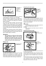
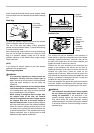
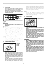
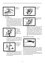
There are crown and cove molding joints which are
made to fit "Inside" 90° corners ((1) and (2) in Fig.
A) and "Outside" 90° corners ((3) and (4) in Fig. A).
(1)(2) (3)(4)
1 2
Fig.A
001556
2
(1)
(2)
(1)
(2)
(2)
(1)
(2)
(1)
(1)
(2)
(3)
(4)
1
001557
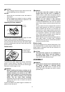
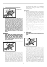
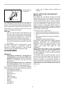
Measuring
Measure the wall length and adjust workpiece on
table to cut wall contact edge to desired length.
Always make sure that cut workpiece length
at the
back of the workpiece
is the same as wall length.
Adjust cut length for angle of cut. Always use several
pieces for test cuts to check the saw angles.
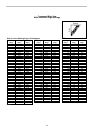
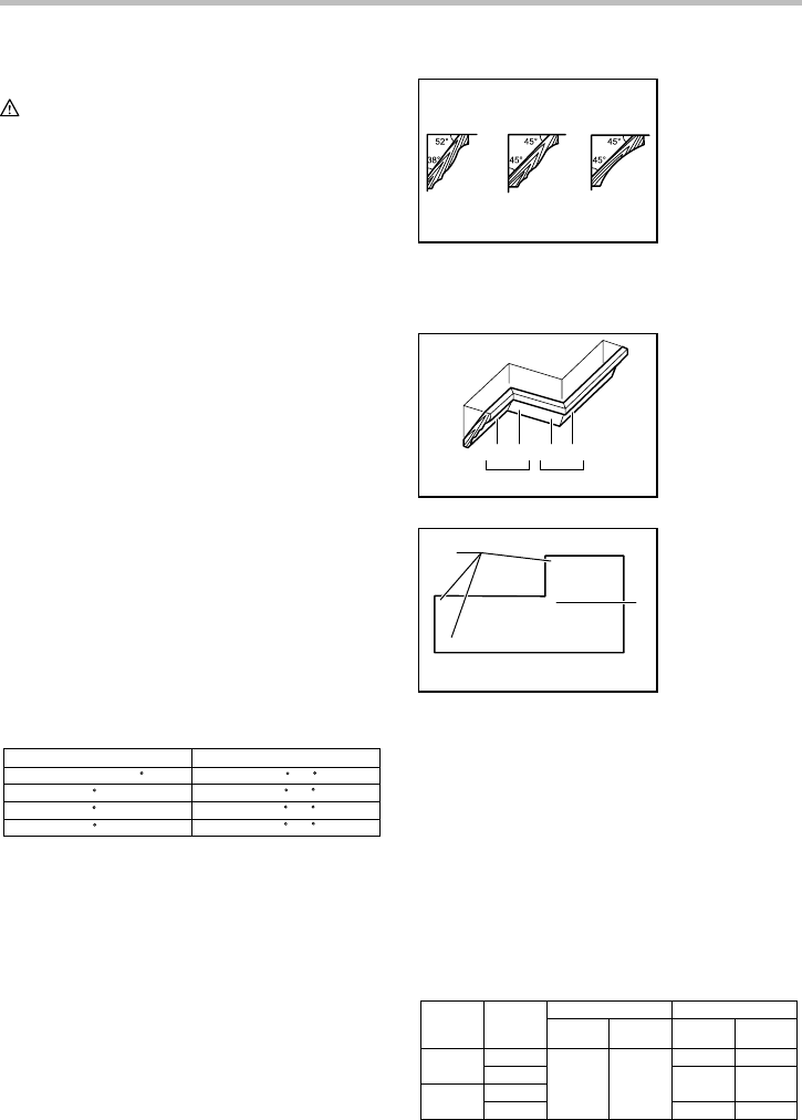
When cutting crown and cove moldings, set the
bevel angle and miter angle as indicated in the table
(A) and position the moldings on the top surface of
the saw base as indicated in the table (B).
In the case of left bevel cut
Molding
position in
Fig. A
Bevel angleMiter angle
For outside
corner
For inside
corner
52/38° type 45° type
Right 31.6°
45° type
Left 33.9° Left 30°
52/38° type
Left 31.6° Left 35.3°
Right 35.3°
Right 35.3°Right 31.6°
(1)
(2)
(3)
(4)
Table (A)
006361
1. Inside corner
2. Outside corner
1. Inside corner
2. Outside corner
1. 52/38 ゚ type
crown molding
2. 45 ゚ type crown
molding
3. 45 ゚ type cove
molding