


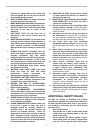

7
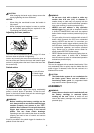
In the interest of your personal safety, always maintain
the blade guard in good condition. Any irregular
operation of the blade guard should be corrected
immediately. Check to assure spring loaded return action
of guard.
WARNING:
• Never use the tool if the blade guard or spring
are damaged, faulty or removed. Operation of
the tool with a damaged, faulty or removed guard
may result in serious personal injury.
If the see-through blade guard becomes dirty, or sawdust
adheres to it in such a way that the blade and/or
workpiece is no longer easily visible, remove the battery
cartridge and clean the guard carefully with a damp cloth.
Do not use solvents or any petroleum-based cleaners on
the plastic guard because this may cause damage to the
guard.
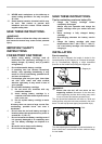
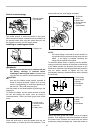
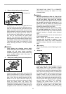
If the blade guard becomes dirty and needs to be
cleaned for proper operation follow the steps below:
With the tool switched off and the battery cartridge
removed, use the supplied socket wrench to loosen the
hex bolt holding the center cover. Loosen the hex bolt by
turning it counterclockwise and raise the blade guard and
center cover. With the blade guard so positioned,
cleaning can be more completely and efficiently
accomplished. When cleaning is complete reverse
procedure above and secure bolt. Do not remove spring
holding blade guard. If guard becomes damaged through
age or UV light exposure, contact a Makita service center
for a new guard. DO NOT DEFEAT OR REMOVE
GUARD.
1
011239
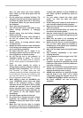
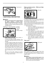
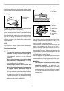
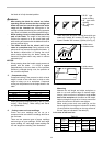
Positioning kerf board
1
2
011240
12
3
45
001800
This tool is provided with the kerf boards in the turn base
to minimize tearing on the exit side of a cut. The kerf
boards are factory adjusted so that the saw blade does
not contact the kerf boards. Before use, adjust the kerf
boards as follows:
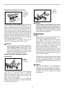
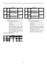
First, remove the battery cartridge. Loosen all the screws
(2 each on left and right) securing the kerf boards.
Re-tighten them only to the extent that the kerf boards
can still be easily moved by hand. Lower the handle fully
and push in the stopper pin to lock the handle in the
lowered position. Loosen two clamp screws which
secure the slide poles. Pull the carriage toward you fully.
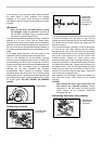
Adjust the kerf boards so that the kerf boards just contact
the sides of the blade teeth. Tighten the front screws (do
not tighten firmly). Push the carriage toward the guide
fence fully and adjust the kerf boards so that the kerf
boards just contact the sides of blade teeth. Tighten the
rear screws (do not tighten firmly).
After adjusting the kerf boards, release the stopper pin
and raise the handle. Then tighten all the screws
securely.
NOTICE:
• After setting the bevel angle ensure that the
kerf boards are adjusted properly. Correct
adjustment of the kerf boards will help provide
proper support of the workpiece minimizing
workpiece tear out.
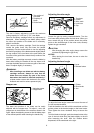
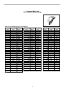
Maintaining maximum cutting capacity
1
2
3
011265
1. Adjusting bolt
2. Guide fence
3. Turn base
1. Saw blade
2. Blade teeth
3. Kerf board
4. Left bevel cut
5. Straight cut
1. Thumb screw
2. Kerf board
1. Blade guard