


TM-353 Page 20 Syncrowave 250
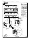
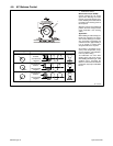
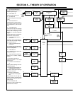
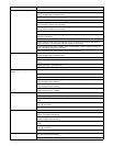
1 Input Terminal Board TE1
Provides means for operation on
different input voltages.
2 Power Switch S1
Provide on/off control of unit.
3 Fan Motor FM
Provides cooling of internal compo-
nents.
4 Main Transformer T1
Supplies power to weld output cir-
cuit, various control circuits, main
control board PC1, and fan motor
FM.
5 Control Board PC1
Controls weld output by changing
the SCR gate pulses (conduction
times) after comparing current
feedback to selected amperage
signal.
Also provides input connections for
switches S3, S5, S6, and S7.
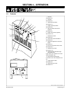
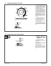
6 Arc Control Switch S6 And
Control R2
R2 selects short-circuit amperage
when S6 is On, and High Frequen-
cy control R13 is Off.
7 Crater Time Switch S7 And
Control R11
R11 selects crater time when S7 is
on, and Amperage Control switch
S5 is in Panel position.
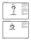
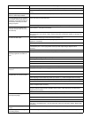
8 Thermostat TP1
If T1 overheats, TP1 opens stop-
ping all weld output.
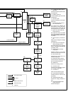
9 Output (Contactor) Switch S3
Selects On or remote contactor
control.
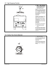
10 AC Balance Control R3
Controls changes to ac output
square wave.
11 Ammeter A1 And Voltmeter
V1
Display weld amperage and volt-
age while welding.
12 Amperage Control Switch S5
And Adjustment Control R1
R1 selects weld output amperage
when S5 is in Panel.
13 Remote 14 Filter Board
PC2/Remote 14 Receptacle
RC1
PC2 protects unit from high fre-
quency, and RC1 connects remote
amperage and contactor controls to
power source.
14 Circuit Breaker CB1
Protects 115 volts ac duplex recep-
tacle RC2 from overload.
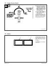
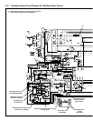
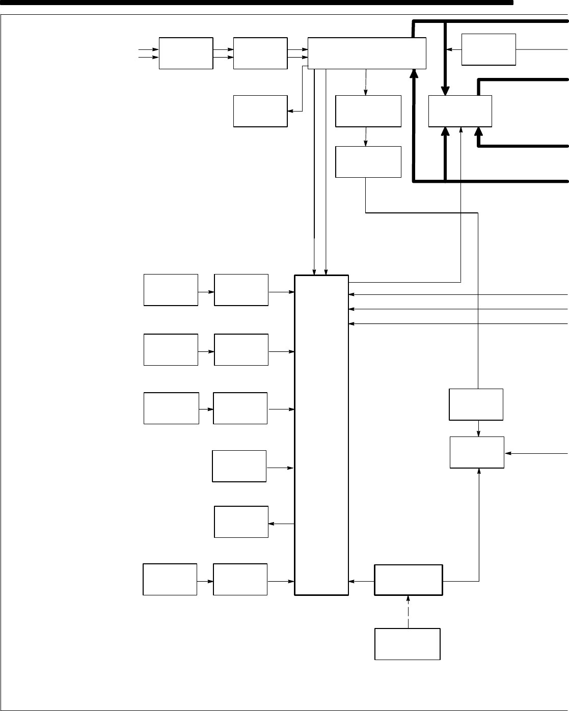
SECTION 5 – THEORY OF OPERATION
1-Phase
Input
Terminal
Board TE1
Power
Switch
S1
Main
Transformer
T1
Circuit
Breaker
CB1
115 VAC
115 VAC Duplex
Receptacle
RC2
Fan
Motor
FM
Control
Board
PC1
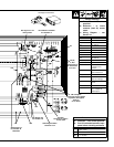
Arc Control
Output
Amperage
Crater Time
Switch
S6
Control
Switch S5
Switch
S7
AC
115 VAC
Thermostat
TP1
Line
Input
Power
DC
Synchronization
Signal
SCR
Gating
Signals
Main
Rectifier
SR1
1
φ1φ
124
31423
15
6
9
12
7
5
8
Arc Control
R2
Amperage
Adjustment
Control R1
Crater Time
Control
R11
AC Balance
Control
R3
10
Ammeter
A1
11
Postflow
Timer
TD1
16
Gas
Valve
GS1
17
6
12
Remote
13
Remote 14
Filter Board
PC2
13
7
1φ
, 10 VAC
(Contactor)
Switch S3
24
Background
Power
Source
Amperage
Control
♦