


TM-353 Page 25Syncrowave 250
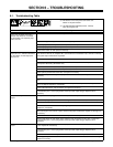
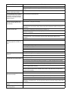
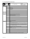
Trouble Remedy
Check Control relay CR2 contacts 4 and 7 for proper operation. Replace CR2 if necessary.
Check coil voltage and connections of gas valve GS1. Check continuity of coils. Replace GS1 if nec-
essary.
No power output at 115 volts ac recep-
tacle RC1; weld output available.
Check circuit breaker CB1, and reset if open (see Section 7-2).
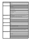
Fan motor FM does not run; weld out-
put available. Effective with Serial No.
KG164875, unit is equipped with Fan-
On-Demand, which only runs when
cooling is required.
Check and clear fan blade obstruction.
Check coil voltage and connections of fan motor FM, and replace if necessary.
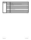
Line fuse opens immediately when
solid-state contactor SR1 turns on in
DC mode only.
Check diode D1, and replace if necessary.
Check SCRs in main rectifier SR1, and replace if necessary. If any SCRs are replaced, Check capac-
itors C7 through C10 for a short or open, and check for proper connections. Replace C7 through C10
if necessary.
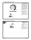
No control of weld output. Check position of Amperage Control switch S5 (see Section 4-7).
Check resistance and connections of Amperage Adjustment control R1; R1 is 1000 ohms ±10%.
Replace R1 if necessary.
Check, repair or replace remote control device.
Effective with Serial No. KB110695, check resistance and connections of HD1; HD1 is 1600 ohms
±10% between pins 1 and 3 of plug PLG3. Check input and output voltages. Replace HD1 if
necessary.
Check control board PC1 and connections, and replace if necessary.
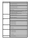
Tungsten electrode oxidizing and not
remaining bright after conclusion of
weld.
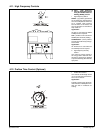
Check position of Postflow Time control R12 (see Section 4-10).
Check and tighten all gas fittings if necessary.
Increase gas flow setting.
Shield weld zone from drafts.
Properly prepare tungsten.
Place High Frequency switch S2 in Start or Continuous position.
Wandering arc - poor control of direc-
tion of arc.
Use proper size tungsten for welding application.
Properly prepare tungsten.
Controls connected to Remote 14
receptacle RC1 do not work properly.
Check, repair or replace remote control device.
Check Amperage Control switch S5 position (see Section 4-7). Check and replace S5 if necessary.
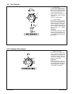
Check Output (Contactor) switch S3 position (see Section 4-8). Check and replace S3 if necessary.
Check position of jumper links 1 and 2 on terminal strip 1T according to Section 6-2.
Check coil voltage and connections of control relay CR2. Check continuity of coil and condition of
contacts. Replace CR2 if necessary.
Prior to Serial No. KF959379, check choke RFC1 connections. Check continuity of RFC1. Replace if
necessary. Effective with Serial No. KF959379 check remote 14 filter board PC2 (see Section 6-6).
Replace PC2 if necessary.
Check control board PC1 and connections, and replace if necessary.
Ammeter A1 not displaying correct
weld output amperage.
Calibrate ammeter as instructed in Section 6-8.
Check ammeter A1 voltage; +1 millivolts dc per 3 ampere of weld output. Replace A1 if necessary.
Check control board PC1 and connections, and replace if necessary.
Effective with Serial No. KB110695, check resistance and connections of hall device HD1; HD1 is
1600 ohms ±10% between pins 1 and 3 of plug PLG3. Check input and output voltages. Replace HD1
if necessary.
Voltmeter V1 not displaying correct arc
voltage.
Check connections for continuity to voltmeter V1. Replace V1 if necessary.
Electronic equipment in welding area
not working properly.
HF interference problem. Check for proper installation, and correct problem (see Section 8).