


TM-353 Page 26 Syncrowave 250
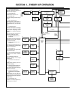
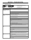
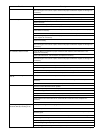
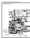
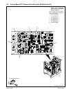
6-2. Troubleshooting Circuit Diagram For Welding Power Source
Y Disable high frequency by placing High Frequency
switch S2 in Off position before testing unit.
R1
V2
V3
V1
V4
V5
V6
V13
V14
V15
V16
Link 1 Link 2
V7
V8
V9
V10
V11
V17
V12
R1
R1
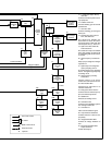
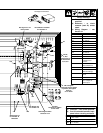
See Section 3-8
for RC1
information
TD1 begins to time out
when CR5 deenergizes
TD3 begins to time out
when CR4 energizes
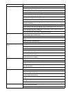
See Figure 9-19
for PC3 circuit
CR3 energizes during spot time
when an arc is detected
CR4 energizes when remote contactor
switch closes
CR2 energizes when
remote contactor
switch closes
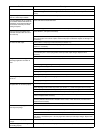
See Section 6-6
for PC2 data
R1
V25