


TM-353 Page 22 Syncrowave 250
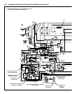
SECTION 6 – TROUBLESHOOTING
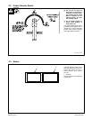
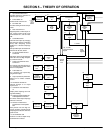
6-1. Troubleshooting Table
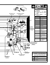
. See Section 6-2 for test points and values and
Section 10 for parts location.
. Use MILLER Testing Booklet (Part No. 150 853)
when servicing this unit.
Trouble Remedy
Prior to Serial No. KG164875, no weld
output; unit completely inoperative –
Effective with Serial No. KG164875,
no weld output; unit completely inop-
erative; PL2 off.
Be sure line disconnect switch is in the On position.
Replace building line fuse(s) or reset circuit breaker(s) if open.
Check for proper electrical input connections (see Section 3-11).
Check for proper jumper link position (see Section 3-11).
Check Power switch S1 and replace if necessary.
Prior to Serial No. KG164875, no weld
output; fan runs – Effective with Serial
No. KG164875, no weld output; fan
runs; PL2 on.
If using remote control, place Output (Contactor) switch S3 in Remote 14 position, and connect re-
mote control to Remote 14 receptacle RC1 (see Sections 3-8 and Section 4-8). If remote is not being
used, place Output switch S3 in On position.
Check, repair or replace remote control device.
Allow a cooling period of approximately 15 minutes. If thermostats TP1 remain open, check continuity
and replace if necessary (see Section 3-3).
Check circuit breaker CB1, and reset if open (see Section 7-2).
Place Output Selector switch S4 in desired position (see Section 4-2).
Check optional preflow timer board TD3, and replace if necessary.
Check optional spot timer relay TD2 for proper connections and resistance. Replace TD2 if
necessary.
Check continuity of Spot Time switch S8. Check condition of contacts. Repair or replace S8 if neces-
sary.
Check SR1, and replace necessary components. If components are replaced, check capacitors C7
thru C10. Replace capacitor(s) if necessary.
Check control board PC1 and connections, and replace if necessary.
Effective with Serial No. KB110695, check resistance and connections of HD1; HD1 is 1600 ohms
±10% between pins 1 and 3 of plug PLG3. Check input and output voltages. Replace HD1 if
necessary.
Unit provides only minimum weld
output.
Check position of Amperage Control switch S5 (see Section 4-7).
Increase Amperage Adjustment control R1 setting if a remote control is used (see Section 4-7).
Check, repair or replace remote control device.
Check resistance and connections of Amperage Adjustment control R1; R1 is 1000 ohms ±10%.
Replace R1 if necessary.
Check SCRs in main rectifier SR1, and replace if necessary. If any SCRs are replaced, Check capac-
itors C7 through C10 for a short or open, and check for proper connections. Replace C7 through C10
if necessary.
Check control board PC1 and connections, and replace if necessary.
Effective with Serial No. KB110695, check resistance and connections of HD1; HD1 is 1600 ohms
±10% between pins 1 and 3 of plug PLG3. Check input and output voltages. Replace HD1 if
necessary.
Unit provides only maximum weld
output.
Check Amperage Adjustment control R1 for proper connections and resistance; R1 is 1000 ohms
±10%. Replace R1 if necessary.
Effective with Serial No. KB110695, check resistance and connections of HD1; HD1 is 1600 ohms
±10% between pins 1 and 3 of plug PLG3. Check input and output voltages. Replace HD1 if
necessary.
Check connections for continuity to shunt device on units with Serial No. prior to KB110695.
Check bypass capacitors C13, C14, C16, C17, C18, and C19 for broken leads, shorts, and leakage.
Replace if necessary.