


TM-353 Page 34 Syncrowave 250
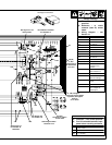
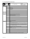
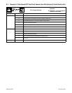
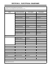
6-7. Remote 14 Filter Board PC2 Test Point Values (Use With Section 6-2 And Section 6-6)
PC2 Voltage Readings
a) Tolerance –
±10% unless
specified
b) Reference – to circuit common
(lead 42) unless noted
Receptacle Pin Value
RC1 A 24 volts ac
B Contact closure to A completes 24 volts ac contactor control circuit
C Command reference; 0 to +10 volts dc output to remote control
D Remote control circuit common
E 0 to +10 volts dc input command signal from remote control
K Chassis common
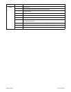
RC2 1 Command reference; 0 to +10 volts dc output to remote control
3 Contact closure to A completes 24 volts ac contactor control circuit
4 Remote control circuit common
5 0 to +10 volts dc input command signal from remote control
6 24 volts ac
RC3 1 Chassis common